BURNET, BRODERICK & CO.
Chicago, Illinois
1858
Burnet & Broderick's Sewing Machine

The sewing machine is now a piece of mechanism of such extended utility and application, that every contribution to its improvement or simplification is to be regarded with due attention and respect and each invention which has for its object the more perfect action and the production of better work deserves to be examined impartially and with care. The illustrations of the present article show a perspective view, Fig. 1 and a front end view, Fig. 2, of a new sewing machine, invented by S. S. Burnet and W. Broderick, of Chicago, Ill. and patented November 30th, 1858, (US 22.160) in following the description of which, we ask the reader to remember the above remark. Upon the table or bed, A, a frame, B and attached arm, B', is secured. These carry the feed motion and needle and their operating parts. Through the top of B, a horizontal bar is placed carrying a belt wheel, C and two crank wheels, D D', the crank wheel, D, serving also as a cam by a small depression being formed at h. To D is attached an arm E which as D is rotated gives a back and forth motion to the rocker, F, that is attached to B' by a pin a and F communicates its motion through a link, G, to the needle carrier H and needle, I. H moves in guides T. The motion of the needle is thus obtained by means the most simple and effective. To D' is secured a link, J, that passing through a slot in A, operates the rocker, K, suspended by the bearing, V, under A and K gives the proper motion to another link, L, that moves the slide, M, in which the shuttle, N, is placed; the shuttle moving in a race-way, h. By these means the motion is obtained shuttle. The thread coming off the spool, 0, passes between two thin flat metal plates in P and a slide on them brings them closer together, or allows them to be further apart to regulate the tension; from P it passes through a small loop, l, thence through an eye or forked wire on G, where the tension is properly raised at different portions of the stitch by a spiral spring, after which it passes to the needle, being guided on the way by the eyes, l' l".
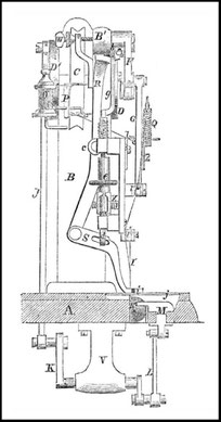
The feed motion is obtained in the following manner; the feed bar, R, is pivoted to the frame at c and it is moved by a small cam, b, on F, which forces it forward and by means of a feed plate, S, the serrated end of which, i, moves the cloth. The feed bar and plate are forced back by the spring, X. In S, is a slot that works over a pin in an arm d, that can be lengthened or shortened by the double screw, e, a little nut on the bottom of which prevents its moving by the motion of the machine and a spring, f, on the upper end of the device elevates the portion, i, from the cloth, as S is being drawn back and at the same time the end of g, which passes over the indentation, h, on D, allows this to be done; when i is pushing the cloth forward or is at rest, the lever, g, keeps it in contact with the cloth, by being all the while on the largest diameter of D. The plates, j, serve to cover up the shuttle and race. The whole machine is operated by a band, U, passing over the pulley, C. A perfect loop is formed by this machine and the shuttle is allowed time to pass through the loop before it is drawn tight, and thereby accomplishes the interlocking of the two threads and the drawing of the stitch tight upon the cloth. Every part is under complete control, the length of feed being regulated by screw, W and the machine operates quietly and with great precision and regularity.
Any further information can be obtained by addressing:
Burnet, Broderick & Co., Chicago, Illinois