
Room 13
SEWING MACHINERY
BEING
A PRACTICAL MANUAL
OF
THE SEWING MACHINE
By J. W. Urquhart, C.E.
PREFACE
The aim of the Author in preparing this little treatise was to confine himself within the limits of such a production as might be read with advantage by that numerous portion of the community engaged in selling and adjusting sewing machines, as well as by the general public using or interested in stitching mechanism. The work is intended to give a concise but accurate and readable account of the invention of sewing machines, with descriptions of the chief types of stitching mechanism in use and also technical directions for the adjustment of specific types of machine. It is hoped that the latter feature of the work will meet a want long felt of a work of reference in cases of difficulties as regards inefficient operation of sewing machines. The book is divided into two sections and those in turn are arranged in chapters. The first section treats of the history and gives elementary principles upon which sewing machines work, with descriptions of the machine. The second section is entirely devoted to practical instructions to users, adjusters and sellers of sewing machines. The Author has necessarily, owing to the limited space at his command, not attempted to include descriptions of any but types of the machine now in use; his aim has been to review essential and leading facts and to produce a handbook that might prove of actual service in the business of daily life He has to acknowledge, with thanks, the able assistance, during the preparation of the work, of the Wheeler & Wilson Manufacturing Company, the Howe Machine Company and the Willcox & Gibbs Company.
London, August, 1880
Contents
Section I
HISTORY AND DESCRIPTION OF THE SEWING MACHINE
CHAPTER I
Invention of the Sewing Machine : an Historical Sketch
CHAPTER II.
The Elements or Stitching Mechanism
CHAPTER III
Shuttle Sewing Machines
CHAPTER IV
Descriptions of Rotating-Hook. Machines
CHAPTER V
Single-Thread Sewing Machines
CHAPTER VI
Proportions of Needles and Thread to Work
Section II
DIRECTIONS FOR ADJUSTING THE VARIOUS TYPES OF SEWING MACHINERY
CHAPTER VII
Wheeler and Wilson Machines
CHAPTER VIII
Singer Machines
CHAPTER IX
Grover and Baker Machines
CHAPTER X
"Little Wanzer " Machines
CHAPTER XI
Weir Machines
*********************************************************
SEWING MACHINERY
SECTION I
HISTORY AND DESCRIPTION OF THE SEWING MACHINE
CHAPTER I
INVENTION OF THE SEWING MACHINE : AN HISTORICAL SKETCH
The invention of what is known as the lock stitch, and of the mechanism by which it is produced, is due to America and dates from about 1844. Elias Howe, the inventor of the shuttle sewing machine, was born in 1819, in Spencer, Massachusetts. When the idea of a sewing machine entered his mind he was twenty years old and a " machinist " in the shop of an ingenious mechanic in Boston. Young Howe overheard a capitalist remark to his employer that an independent fortune would be insured to the inventor of a sewing machine and forthwith the idea seized him that a stitching machine was practicable. But the only immediate effect upon him of the conversation in the shop of Mr. Davis was to induce a habit of reflecting upon the art of sewing, watching the operation as performed by hand and wondering whether was within the compass of the mechanical arts to do it by machinery.
1
His uppermost thought was, what a waste of power to employ the ponderous human arm and all the intricate machinery of the process, in performing an operation so simple and for which a robin's strength would suffice ! Why not draw twelve threads through at once, or fifty ? And sometimes, while visiting a shop where army and navy clothing was made, he would look at the heaps of unsewed garments, all cut alike, all requiring the same stitch, the same number of stitches and the same kind of seam and say to himself: " What a pity this cannot be done by machinery ! It is the very work for a machine to do ". It was not until Howe was four years older, and married, with a family to support upon nine dollars a week, that the pressure of poverty, and the extreme fatigue he suffered by reason of his daily work being too heavy for him, caused his mind to again concentrate itself upon the idea of a sewing machine, which he had heard, four years before, would be an " independent fortune " to the inventor. He wasted many months on a false scent. When he began to experiment, his only thought was to invent a machine which would do what he saw his wife doing when she sewed. He took it for granted that all sewing must be done in this way and his first device was a needle pointed at both ends, with the eye in the middle, that should be caused to work up and down through the cloth, and carry the thread with it at each thrust. Howe brooded over this impracticable conception for some time, aud cut many a basket of chips in his endeavour to make something that would work such a needle so as to form the common hand stitch, but he could not accomplish it.
2
One day, in 1844, the thought flashed upon him: is it necessary that a machine should imitate the performance of the hand; may there not be another stitch ? This was the crisis of the invention. The idea of using two threads, and forming a stitch by the aid of a shuttle and reciprocating needle, with the eye near the point, soon occurred to him, and he felt that he had invented a sewing machine. It was in the month of October, 1844, that he was able to convince himself, by a rough model of wood and wire, that such a machine as he projected would sew. The practicability of the invention could not be exhibited or tested except by a machine of steel and iron, with the exactness and finish of a clock, and Howe, who was reduced about this time to the greatest hardships, could not provide even the raw material for such a machine. Fortunately for the poor inventor, however, there was living at Cambridge (U.S.A.) a young friend and schoolmate of former days, a wood and coal merchant, named George Fisher, who had recently inherited some property and was not disinclined to speculate with some of it. The two friends had been in the habit of conversing together upon the project of a sewing machine. When, therefore, the inventor had reached his final conception in 1844, he succeeded in convincing George Fisher of its feasibility, which led to a kind of partnership between them for bringing the invention out. The terms of this partnership were these: George Fisher was to receive into his house Elias Howe and his family, board them while Elias was making the machine, give up his garret for a workshop and provide money for material and tools to the extent of five hundred dollars; in return for which he was to become the proprietor of one-half the patent, if the machine proved to be worth patenting.
3
Early in December, 1844, Elias Howe moved into the house of George Fisher, set up his shop in the garret, gathered materials about him and went to work. It was a very small, low garret, but it sufficed for one zealous, brooding workman, who did not wish for gossiping visitors. All the winter of 1844-45 Howe worked at his machine. His conception of what he intended to produce was so clear and complete that he was little delayed by failures, but worked on with almost as much certainty and steadiness as though he had a model before him. In April he sewed a seam with his machine. In the middle of May, 1845, he had completed his work. In July he sewed by his machine all the seams of two suits of woollen clothes, one suit for Mr. Fisher, and the other for himself, and this sewing outlasted the cloth. This, Howe's original machine, may still be seen at 28, Union Square, New York and is represented in the frontispiece to this work. Mr. Howe, like many other inventors, found that when he had completed his machine his difficulties had but begun. After he had brought the machine to the point of making stitches, he went to Boston to get a tailor to come to Cambridge, and arrange some cloth for sewing and give his opinion as to the quality of the work done by the machine. The comrades of the man to whom he first applied dissuaded him from going, alleging that a sewing machine, if it worked well, must necessarily reduce the whole fraternity of tailors to beggary and this further proved to be the unchangeable conviction of the tailors for the next ten years. It is quite probable that the machines first made would have been destroyed by violence, but for another fixed opinion of the tailors, which was that no machine could be made that would really answer the purpose.
4
This machine was then publicly exhibited and at the Quincy Hall Clothing Manufactory, Mr. Howe challenged five of the swiftest sewers in the establishment to a race with his machine. Ten seams of equal length were prepared, five of which were given to the girls, and the other five were taken in hand by Mr. Howe. The result was that the machine had run up the five seams when the hand sewers were little more than half through with their five. Upon reading testimony like this the wonder is that manufacturers did not at once set Howe at work making sewing machines, but not one was ordered. Not a tailor encouraged him by word or deed. Some objected that the machine did not make the whole garment; others dreaded to encounter the fierce opposition of the journeymen; while not a few really thought it would beggar all hand sewers, and refrained from using it on principle. It was the old story: " We are doing well as we are and fear to make such a change ". But the inventor was not disheartened by the result of the introduction of the machine. The next step was to get the invention patented and Howe again shut himself up in George Fisher's garret for three or four months and made another machine for deposit in the Patent Office. Late in the summer of 1846, the model and documents being ready for the Patent Office, the two partners went to Washington, when the sewing machine was exhibited at a fair, with no result except to amuse the crowd. On September 10th, 1846, the patent was issued and soon after the young men returned to Cambridge. George Fisher was now totally discouraged; he had risked in all about two thousand dollars and he saw not the remotest probability of the invention becoming profitable.
5
Elias Howe moved back to his father's house, and George Fisher considered his advance in the light of a dead loss. It now occurred to Howe that since America had rejected the invention, he should offer it to England. In October, 1846, his brother, Amasa B. Howe, with the assistance of their father, took passage in the steerage of a sailing packet, and conveyed one of the machines to London. An Englishman was found who had faith enough in the American sewing machine to invest money in it. In Cheapside, Amasa Howe came upon the shop of a manufacturer of corsets, umbrellas, valises, carpet bags, and shoes, who examined and approved of the machine. But the bargain made on this occasion, through the agency of Amasa B. Howe, was signally bad for the inventor. He sold for two hundred and fifty pounds sterling the machine he had brought with him, and with it the right for the purchaser to use as many others in his own business as he desired. There was also a verbal understanding that this manufacturer was to patent the invention in England, and, if the machine came into use there, he was to pay the inventor three pounds on every machine sold; he further proposed to engage the inventor to adapt the machine to the making of corsets, offering him a salary of three pounds a week, and to defray expenses of material. Amasa B. Howe returned to Cambridge with this proposal, and America being still insensible to the charms of the sewing machine, Elias Howe accepted the offer, and the brothers set sail for London on February 5th, 1847, where they were soon after joined by the inventor's wife and family.
6
After eight months of labour Howe succeeded in adapting his machine to the work required and when this was done his employer required him to do the various repairs, an insult which the American naturally resented, and he was in consequence discharged. The most painful part of the story of poor Howe now commences. From a chance acquaintance, Charles Inglis, a coachmaker, who proved to be a true friend, he leased a small room for a workshop, in which, after borrowing a few tools, he began to construct his fourth sewing machine. Long before it was completed he saw that he must reduce his expenses or leave the machine unfinished. From three rooms he removed his family to one and that a small one, in the cheapest part of Surrey. Nor did that economy suffice ; and he resolved to send his family home while he could, and trust to the machine on hand for the means to follow them. "Before his wife left London," testifies Mr. Inglis, " he had frequently borrowed money from me in sums of five pounds and requested me to fm4 him credit for provisions. On the evening of Mrs. Howe's departure, the night was very wet and stormy, and her health being delicate, she was unable to walk to the ship. Howe had no money to pay the cab hire, and he borrowed a few shillings from me to pay it, which he repaid by pledging some of his clothing. Some linen came home from his washerwoman for his wife and children on the day of her departure, but she could not take it with her on account of not having money to pay the woman." After the departure of his family the solitary inventor was still more severely pinched, but at the expiration of three or four months the machine was finished.
7

8
It was worth fifty pounds. The only customer he could find was a working man, who offered five pounds for it if he were granted sufficient time to pay it in. The inventor was obliged to accept this offer. The purchaser gave his note for the five pounds, which Charles Inglis succeeded in selling to another mechanic for four pounds. To pay his debts and his expenses home, Mr. Howe pawned his precious first machine and his letters patent, and again took passage to America, along with his English friend, Charles Inglis. In April, 1849, Elias Howe, with half-a-crown in his pocket, landed in New York, after an absence of two years. He was obliged to seek employment in the machine shops, which he luckily found without delay. He had no sooner settled to work, however, than the news came to him from Cambridge that his wife was dying of consumption, but he had not the money wherewith to visit her. A few dollars afterwards came from his father, and Howe had time to reach his wife and to see her during her last moments. The natural gaiety of poor Howe's disposition was now quite quenched by the severity of his many trials, and he appeared exceedingly downcast and worn. Soon after this, as a crowning misfortune, came the intelligence that the ship in which he had embarked all his household goods had been wrecked off Cape Cod, and was a total loss. From this point, which may be considered the lowest depth of Howe's misfortunes, he received help from his friends, and he soon discovered that his first machine on the shuttle principle was being imitated and sold about America, and that while he resided in London several ingenious mechanics had turned their attention to the making of sewing machines.
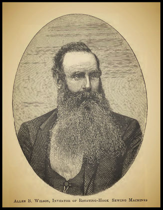
9
Howe now prevailed upon a capitalist to join him in defending his rights, and many lawsuits followed, the outcome of which was that Howe was acknowledged to be the first inventor of the shuttle sewing machine. Shortly afterwards he was established in New York as a manufacturer of sewing machines, and in a few years, having bought up the remainder of his patent, was the worthy recipient of a princely revenue derived from their sale. In the year 1867 he was decorated with the Cross of the Legion of Honour by France, but he did not long enjoy the honours and rewards which his invention had brought him, for on the 3rd of October, 1867, Elias Howe died at Brooklyn, New York, to the deep regret of his innumerable friends, who not only honoured him as the inventor of the sewing machine, but also for the many excellent personal characteristics he possessed. Allen B. Wilson, the inventor of the rotating hook lock-stitch machine, was born in the year 1827 and became, at twenty years of age, a journeyman cabinetmaker in Adrian, Michigan. In 1847 Wilson conceived the notion of a sewing machine and had some definite ideas as to the means by which the apparatus should work. The inventor's own words graphically describe his position at this time and the difficulties under which he laboured. I was in needy circumstances, earning but little more than enough to board and clothe me. I was taken sick early in the spring of 1847, with fever and ague, which greatly reduced me; I have never fully recovered from it. The inventor then goes on to describe his difficulties in attempting to put his ideas into the form of a sewing machine and after enduring great privation we find him at Willitt, Courtland Co., New York .
10
I remained there until May, 1848, working while able and giving much thought to my sewing machine, which I was then very desirous of building. I then went to work in a cotton mill at Homer and got money enough to reach New York City on the 15th of J\me, 1848, destitute and a stranger. . . . Not being able to do hard work and being destitute of the means of living, I hired out as a cook on a coasting sloop running on the Long Island Sound. ... I left the sloop at Providence and worked there a few weeks. I then went to Boston, where I worked a few weeks more, by which I was enabled to save about twelve dollars. I went to Pittsfield the last of August, 1848 and hired out the same day to Barnes and Goodrich, cabinet-makers. As the fall was approaching, it occurred to me that as the evenings became longer, if I could only get the evenings to myself, I would have time to make the sewing machine, the plan of which I had so long in my mind. No favourable opportunity occurred until I went to work for Mr. Barnes individually, which was about Feb. 1st, 1849, when it was specially agreed that I should have the evenings to myself and a right to work in the shop in the evenings for myself. I had previously, as early as November, 1848, made full drawings of all the parts of my projected sewing machine and shown them to two or three of my most intimate friends. . . . They laughed at me and I concluded not to say anything more about it until it was done. I began the construction of a working machine almost the first evening I worked for Mr. Barnes and completed it about the 1st of April, 1849. Not being a machinist by trade and having no means wherewith to procure the assistance of machinists, it was necessarily of rude and imperfect construction and did not illustrate in the best manner the principle and mode of operation involved in my invention; but, notwithstanding its imperfections, it had made garments of various kinds and had been exhibited to many persons.
11
12
" Up to this time I had never seen or heard of a sewing machine other than my own. In May, 1849, I moved to North Adams, Mass., and built a second and better machine of the same kind. I received no encouragement or assistance, however, but, on the contrary, discouragement and ridicule ; and as I had no money, it became a serious question how I should obtain letters patent for my invention. At last I "induced Joseph N. Chapin, of North Adams, to purchase one-half interest in the invention for two hundred dollars. This was the best I could do. I spent all that, and about two hundred dollars more, in procuring the patent, which was dated November 12th, 1850." Mr. Wilson then records how he and Mr. Chapin fell into the hands of New York swindlers, who, pretending to have a right to some parts of the invention, induced the partners to make over to them half the patent, to avoid ruinous legal proceedings. This was done, but the hollowness of the claims of the persons mentioned became in a month or two so obvious, that Messrs. Wilson and Chapin were enabled to free their property, which was, after much trouble, put into the hands of a small party of commercial men, who ultimately did Mr. Wilson justice, and founded the Wheeler and Wilson Sewing Machine Company. The first machine brought out by Wilson operated by means of a two-pointed shuttle, and a feeding device of the most ingenious description. The Howe machine at first operated by means of a " baster plate," in which were inserted a series of pins, upon the points of which the cloth was fastened.
13
This plate was moved forward at each stitch to form the feed, as shown in the frontispiece. (See description, p. 27.) Mr. Wilson arranged his machine so that the material could be pressed upon the cloth plate by a spring foot, and added to the stitching mechanism a feeding apparatus which has four motions, and carries the cloth in any required direction, so that the seam may be straight or curved at will. The basis of all modern feeding mechanism, upon which so much depends, is thus due to Allen B. Wilson. But by far the most wonderful invention in the construction of sewing machines is Wilson's Rotating Hook, which he applied to his machine shortly after its introduction. This device, which is explained at p. 46, performs the functions of a shuttle by seizing the upper thread, and throwing its loop over a circular bobbin containing the under thread. The motion is continually in one direction, and the reciprocating movements of the shuttle entirely avoided. A further development of the same invention, which is exhibited and explained at p. 55, has been made by Mr. House, in the employment of the Wheeler & Wilson Company. James E. A. Gibbs, the inventor of the Single-thread Rotating-Hook Machine, has kindly furnished the author with the following account of this ingenious invention:—"My attention was first called to the subject of sewing machines in the year 1855, by seeing a plain woodcut of a Grover & Baker machine in a newspaper advertisement, and being of a mechanical turn of mind, it at once excited my curiosity to know how it could possibly sew. As I was then living in a very out-of-the-way place (Pocahontas Co., Virginia, U.S.), far from railroads and public conveyances of all kinds, modern improvements seldom reached our locality and not being likely to have my curiosity satisfied otherwise, I set to work to see what I could learn from the woodcut, which, was not accompanied by any description.
14
"I first discovered that the needle was attached to a needle arm and consequently could not pass entirely through the material, but must retreat through the same hole by which it entered. From this I saw that it could not make a stitch similar to hand work, but must have some other mode of fastening the thread underneath, and among other possible modes of doing this, the chain stitch occurred to me as a likely means of accomplishing the end. " I next endeavoured to discover how this stitch was or could be made, and from the woodcut I saw that the driving shaft, which had the driving wheel on the outer end, passed along under the cloth plate of the machine. I knew that the mechanism which operated on the stitch must be connected with, and actuated by, this driving shaft. After studying the position and relations of the needle and shaft with each other, I conceived the idea of a revolving hook on the end of the shaft, which might take hold of the thread, and manipulate it into a chain stitch. My ideas were, of course, very rude and indefinite, but it will be seen that I then had the correct conception of the invention afterwards embodied in my machine. " Having no further interest in view than to satisfy my curiosity how sewing by machinery could be done, and caring little whether I had the correct idea or not, I gave the matter no further attention or thought until during the month of January, 1856. At this time, while on a visit to my father in Rockbridge Co., Virginia, I happened to go into a tailor's shop where there was a Singer's sewing machine working on the lock-stitch shuttle principle.
15
I was very favourably impressed with its utility, which was far beyond my previous impressions of the development of the art, but at the same time I considered the machine entirely too heavy, complicated, and cumbersome, and also that the price was exorbitant. These considerations led me to apply myself to inventing and producing a more simple, cheap, and useful machine. As soon as I reached home in Pocahontas Co. I began to apply my mind to this subject. I first made a small imperfect hook on the end of a piece of wire, by which I demonstrated that the chain stitch could be made by a hook revolving on the end of a driving shaft, and first thought of making a machine in this way, but after producing some samples of a chain stitch and testing them, I became dissatisfied with the stitch, and also still labouring under the delusion that probably the Grover and Baker machine was constructed in that way, I concluded to turn my attention to the lock stitch, and made a rude model out of wood of a shuttle lock-stitch machine. My family was at this time dependent upon my daily labour for support, so that I had very little time to spare for my experiments, working only at nights and in bad weather. I also laboured under great disadvantages for want of tools and materials, having to make my own needles, and constructing my shuttles of wood, as I was then a carpenter only. By the 1st of April, 1856, I had completed my model, and succeeded in interesting my employers in my invention so far as to induce them to furnish the capital wherewith to take out letters patent and develop the machine. During the month of August of the same year I came to Washington to take out my letters patent and while there I examined the models in the office, and also some of the machines then in the market.
16
" I ultimately fell back upon my old idea of a single thread machine with greater confidence in its success, but while making the first one, the idea occurred to me to make the hook stationary, and to vibrate the needle instead. This needle, however, I found to be already in use by others, and I finally produced a sewing machine with a rotating hook or looper, and a needle having a vertical motion only." With the assistance of Mr. Ruckman, this machine was at first manufactured by the firm of Emory, Haughton & Co., of Boston. Mr. Gibbs is the inventor of several improvements in sewing machines, but the final outcome has been the Willcox and Gibbs machine, described at p. 74. Several other kinds of stitches form the subjects of independent inventions, but the limits of this treatise preclude the giving of fuller historical particulars. Those mentioned may be accepted as the only stitches used for general purposes, the double-chain stitch, mentioned at p.152, being now almost obsolete. We have, therefore, two distinct stitches, one of which is formed by means of interlooping a single thread beneath the fabric, and the other by interweaving with a second thread, also beneath the cloth. Each of these stitches possesses certain advantages for given kinds of work. The single-thread, or, as it is generally termed, the chain stitch, is elastic, and seldom gives way when the fabric is wetted; when made with a good and suitable class of thread, it lies close to the under side of the fabric and is not liable to injury by friction. When the seam is worked with the thread at a considerable tension, it does not tend to unravel, even if broken at several points.
17
In addition to these advantages a single-thread seam is preeminently suited to those classes of goods which ladies frequently take to pieces for reshaping or other purposes, because the seams are readily removed by releasing the finishing end and drawing out the thread in one continuous length. The lock stitch, made by the shuttle or by the rotating hook, is essentially an elastic stitch, and, like the chain stitch, withstands the contracting effects of water when the tension has been properly adjusted. It lies close to the fabric upon either side, and possesses great strength. The tendency to unravel when broken at several points of a seam depends to a considerable extent upon the kind of fabric ; an inelastic fabric, in which the needle-holes exhibit no tendency to close, brings out all the defects of this and every other system of sewing. A great deal depends upon the accuracy with which the interlocking point has been adjusted to fall in the centre of the goods. In a woollen fabric the lock stitch does not tend to unravel even if broken at several points. It is difficult to draw a comparison between machine and hand- stitching. Hand work is always irregular, no matter how well performed, and is constantly subjected to strains at particular points, while the machine work, being regular, receives the strain upon larger portions of the seam and suffers less. Lock-stitching is undoubtedly better adapted for ordinary work than hand-stitching, but good hand work stands wear and tear better than the single-thread stitch made by machine, and usually wears better than lock-stitching carelessly and loosely performed. These stitches are described more fully in the following chapter.
18
CHAPTER II
THE ELEMENTS OF STITCHING MECHANISM
The essential elements of a sewing machine, judging from the modern types of construction, consist of:
1st. A needle, having its eye near to its point, carrying a bight of thread into and through the cloth.
2nd. A mechanical device beneath the cloth by means of which the thread may, while under the material, be manipulated so as to make a chain, loop, or stitch, or interwoven with a second and under thread to form what is known as the lock stitch.
3rd. A mechanical device above or beneath the fabric known as a "feeder," by means of which the cloth may be moved forward the required distance on the completion of each stitch.
In addition to these indispensable elementary conditions, a flat horizontal cloth plate is provided, through an aperture in which the needle works vertically, while through a second aperture the feeder, if an under one, must act upon the fabric being sewn.
Formation of Machine Stitches. To form the single thread or chain stitch referred to, a " looper " is employed, the action of which may be vibrations in a given arc, or rotation continuously in one direction.
19
To form the double-thread or lock stitch as above, a shuttle charged with thread is employed, or a rotating hook is designed to take its place by throwing the upper thread in a loop over a bobbin of the under thread. In the single-thread chain stitch the action is as nearly as possible as follows: The needle descends through the fabric, carrying a bight of the thread with it, and the point of the looper begins to vibrate or revolve towards the descending needle. When the needle has reached the extremity of its down stroke it begins to rise, and the immediate result is that a loop of the previously tight thread bight is thrown out from the side of the needle, sufficiently large to allow the rapidly approaching looper to enter it. The needle now rises up through the fabric, beneath which the looper detains the upper thread. If the looper be of the vibrating kind, its action is simply to retain the loop, and to expand it over the path of the needle when it next descends. In this way a fresh loop is secured while the eye of the needle is below the preceding loop ; the usual chain is the result, the first loop being tightly drawn up to the cloth while the looper is in the act of expanding its successor. If the looper be of the rotating description, its action is substantially the same, but a complete twist is given to the loop in the process of expanding. This twisted loop possesses certain advantages over the untwisted loop just mentioned. To form a lock stitch, the needle descends as before, and in rising throws out from its side a slack loop in the same way. If, now, the machine be a shuttle one, the shuttle, which has a reciprocating motion imparted to it across the path of the needle, approaches its point, enters the loop referred to and expands it while the needle rises, passing quite through it, by reason of its being virtually disconnected with its carriage.
20
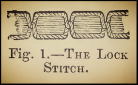
The stitch is complete when the needle has risen to its highest point, and the upper thread is locked with the under thread in the centre of the cloth (Fig. 1). If the machine be a rotating-hook one, the same loop is thrown out and seized by the point of a peculiarly shaped hook, which in the progress of its revolution carries it over and around a cymbal-shaped bobbin containing the under thread. In the most recent form of this machine the loop is cast off the hook and pulled up into the material, completing the stitch. The chain stitch has a plain regular appearance on the upper side of the fabric, while it resembles a chain on the under side. The lock stitch has a plain and Stitch. regular appearance alike on both sides of the fabric, the interlocking point being in the body of the goods. Machine Needles.—Thus the action of all sewing machines depends entirely upon the loop thrown out by the needle when it begins to rise from its lowest point. To facilitate the formation of this loop on one side of the needle only, the latter, on the side turned away from the shuttle, has a long and deep groove, wherein the thread lies almost free from friction, and the loop side is plain excepting a short groove made near to the eye. All sewing machine needles have necessarily a shank or stout stem by which they are secured in the movable arm of the machine, and are made pointed with a uniform thickness throughout the portion passed through the cloth.
21
For ordinary sewing the needles are pointed as in hand needles, but for leather they are given a chisel-shaped point, the more readily to cut their way through it: the same points are frequently turned at an angle to the line of the eye, which has certain advantages for some classes of work. Machine needles are either straight or curved; the carved needles are used in needle arms vibrating in arcs.
Feeding Mechanism. The automatic feeding of the material comes next in importance to the making of the stitch. In the first forms of the sewing machine (see frontispiece) the cloth was fastened upon pointed pins projecting from a "baster plate" or feeder, which was moved forward after each stitch, carrying the cloth with it under the needle. As this movement was quite positive, the fabric could not be turned about to any considerable extent to form curved seams of stitching, and the device necessarily impeded the progress of the sewing machine when first introduced. Later on the idea of feeding by means of a vibrating needle was tried, and finally the present form of feed was invented. In some of the first machines fitted with the " four motion " feed, as it is termed, the material was moved forward by a serrated spring foot pressing upon it from above. This foot had four motions, two of which were positive. It first fell upon the fabric with pressure, and then pulled it away from the operator the required distance at each stitch ; the other two motions were given by springs. This is called a " top feed," and is even yet applied to more than one type of sewing machine. The four-motion feed is, however, more advantageously applied to work the fabric forward from underneath the cloth plate, pressure being continuously applied from above.
22
Two of the motions are always positive, and in most instances the fall and draw-back motions are given by springs. The feed, in operation, first rises and sets its teeth into or against the fabric pressed against the cloth plate from above. It then moves forward from or to the right of the operator, carrying the cloth with it, when the teeth fall below the level of the plate and the feed bar finally draws back for a fresh stitch. The length of the stitch can be regulated to a nicety by extending or curtailing the backward movement of the feeding surface. By means of this most ingenious device (Historical Sketch, p. 14), the cloth is free to be turned upon the needle as a centre to any required angle, and the work may with the utmost ease be sewed in curved or straight lines while the machine is in motion. In addition to these advantages of the four-motion feeder, its progressive motion is in a straight line, and work may therefore be sewed in perfectly straight lines without much guidance from the hand, while it is at the same time quite free to receive other motions at will. In some forms of the sewing machine a feed wheel, with serrated periphery, is employed. This edge projects slightly above the level of the cloth plate from beneath, and the fabric is kept pressed upon it as usual by a spring foot. The wheel feeder is then caused to revolve a given distance at each stitch. This device is well suited for leather stitching, although the fourmotion feed has to a great extent taken its place in this application.
23
Minor Parts of the Sewing Machine. Among the minor devices used in conjunction with the sewing machine spoken of, may be mentioned the tension wheel, which is so arranged that the upper thread may by its movements be kept in the strained condition necessary for tight stitching. Tension may be, and is, put upon the upper thread in a variety of different ways, and is usually adjustable at will. The take-up is a device applied to most lock-stitch machines. Its function is to pull up the loop as soon as it has been passed over the under thread receptacle, shuttle or spool.
The presser foot is merely a device for keeping a constant or intermittent elastic pressure upon the fabric while being sewn. It usually covers about a square inch, and the needle in most instances plays through it. The presser is placed so as to cover the area occupied by the feed surface when moving the stitch forward. The degree of pressure is usually adjustable at pleasure, and the foot may be raised when required to commence or finish stitching. The main overhanging arm of the sewing machine, from which the needle operates vertically upon the fabric, carries also the presser bar, spring, and foot. In the machine illustrated at p. 38 the needle arm is separate from the presser arm, and vibrates as a whole. The upper thread is usually wound off the ordinary wooden spool, which is placed upon a pin where it revolves freely, or the thread is wound off the spool without causing the latter to rotate.
The under thread, on the other hand, as used in lockstitch machines, is in most instances wound off the ordinary wooden spool on to a small metallic reel to be fixed in the shuttle, or into a disc-like spool for use in hook machines. Ready-wound "copes" of under thread are sometimes used in shuttles. Motion is given to all the parts of the machine from one point.
24
The power is usually treadle or hand motion, and steam in manufacturing houses where great numbers of machines are at work at once. All the parts of the machine are usually actuated off one shaft, and one revolution of the shaft generally completes one stitch.
Stands and Treadles. These are so common and their construction so easily comprehended, that no space need be devoted to a consideration of them here.
25
CHAPTER III
SHUTTLE SEWING MACHINES
The sewing machine in its first form, as invented by Elias Howe, made the lock stitch by means of a shuttle, as explained in the chapter treating of the elements of stitching mechanism. The Howe machine of to-day is, however, only one of the numerous developments of the original invention. A great number of makers produce shuttle machines differing in construction from Howe's, but as the principle upon which all these machines work is the same, and as the Howe is a noteworthy example of a first-class powerful sewing machine, possessing all advantages, the section on Shuttle Machines is almost exclusively confined to a description of it. This manner of treating the subject is also in accordance with the history of the sewing machine.
The Howe Shuttle Machine. In the frontispiece to this volume the reader is presented with a general view of the first sewing machine, as invented and made by Elias Howe (History, p. 6). The shuttle machine of to-day has a very different appearance, and varies in construction; but a short description of the first sewing machine may not be uninteresting, as exhibiting the progress which has been made of late years in stitching mechanism.
26
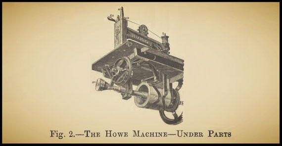
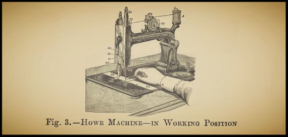
Referring to the frontispiece, it will be observed that the machine is built upon a firm base, a, which carries a strong angular overhanging arm, b. Through the side and free extremity of this arm works a shaft, c, to which is attached the fly-wheel, d, driven by hand at e. The thread for the top stitch is taken continuously from the reel, r, and fed to the curved needle, a, through a spring, b. The needle works through the cloth at c. The latter is carried upon pins, d. The needle arm, g, and the baster or feed plate, h, work so that the plate moves the cloth forward one stage at the completion of each stitch. The shuttle is driven by a driving rod, j, which is caused to vibrate backwards and forwards by means of the cam, l. The cam, I, screwed upon the sleeve, q, actuates the lever, p, which action gives a rocking motion to the short shaft, o, and the needle arm, on being connected to this, vibrates, carrying the needle into and out of the cloth at each revolution of the hand wheel. Such is the sewing machine produced by Elias Howe when he lodged in the house of George Fisher (History, p. 5). The construction and arrangement of the various parts bear a very strong resemblance to the shuttle machine of to-day, but the inconvenient position of the needle arm is, of course, changed. The model as it stands shows that Howe had in his mind all the essential elements of a sewing machine. A Howe machine of approved construction, to which the following description refers, is built upon a firm cast-iron base. To this base the overhanging arm of the machine is bolted. The under parts claim attention first, because they give motion to the needle arm, which is above the base, and to the shuttle arm, which is beneath the base, as exhibited in Fig. 2, which shows the machine tilted up so as to expose the working arrangements.
27
28
Two castings, or hangers, are carried down from the base, in which works the main shaft, upon the end of which is fixed the driving wheel as shown. The actuating cams, of peculiar shape, which revolve with the shaft, and give a reciprocating motion to the needle and shuttle levers respectively, are shown screwed to the shaft. The needle lever is pivoted at the angle of the fixed arm as shown, and upon its extremity, revolving in the right-hand cam, a steel friction roller works. The shuttle lever is pivoted upon a stud, and kept in position by a washer and pin.
29
Its shorter arm is also fitted with a friction roller; its longest end engages with and drives the shuttle carrier through the angle link shown behind the feed wheel. The form of feeding apparatus employed consists, as will be observed, of a wheel with serrated periphery, marked 162. This wheel feeder is actuated by a pair of clutches, 172, hinged upon the hub, and acting against the antagonistic spring, 173. A lever, 159, rides upon the feed cam, 182, and communicates motion to the feed clutches. The feed wheel, which projects slightly above the cloth plate, is thus caused to move forward a short distance during each revolution of 1 the shaft. The cam, 182, is tapered in form, for the purpose of adjusting the stitch, or throw, to the length required. This is effected by screwing or unscrewing the thumb nut, 184, which causes the cam to advance to, or recede from, the rider, 159. The rider is constantly urged against the cam by the antagonistic spring, 170. A great number of the Howe machines are fitted with the four-motion feeder, modified from the original invention referred to in Chapter I. The disposition of the various parts will be understood by reference to Fig. 3. The needle arm, as will be seen, engages with the needle bar, 40, behind the head of the fixed arm. The serrated surface of the feed is shown at 92, and the presser foot, turned aside out of the way, at 102. Nos. 112 and 113 show slide plates, which cover the shuttle race and shuttle, to be further explained. The tension wheel, 119, is of peculiar construction. It is shown full size in Fig. 4, where the thread is first observed to be passed into a spring thread guide, 124, where it is gently clasped to make it retain hold upon the pulley. The projection, 118, serves the same purpose.
30
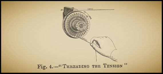
Fig. 5 exhibits the tension wheel removed from its stud, 126. Behind the wheel, at 126, is placed a thick felt washer, and over it and under the metallic washer, 122„ another felt disc. The thumb nut, 128, serves to adjust the pressure upon the wheel, and consequently the degree of tension put upon the thread. Returning now to Fig. 3, the course of the upper thread may be noted, a is a spool of thread, placed so as to run freely upon the spool pin, 5. The thread is then passed around the tension wheel and under the thread controller, 19, over the top of the needle bar, 40, and in the catch of the take-up lever, 32, which is constantly pulled against the thread by an antagonistic spring. It next passes through the groove, 42, and the lower thread guide, 44, to the needle eye as shown.

31
A back view of the top of the needle and presser bars is given in Fig. 6. The lever projecting to the right is the presser raising and swivel handle, which, by means of a cam acting upon the lifter plate, 58, raises the bar against a spring. The steel plate, 17, adjustable by the screw, 18, serves to take up any wear of the plate, 58, and to prevent the presser foot from swerving.

32
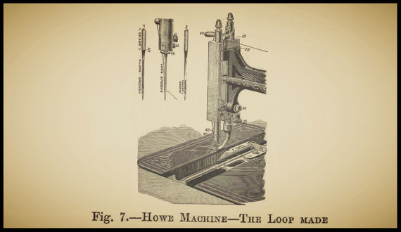
Fig. 7 exhibits the shuttle race and the shuttle, 61, in position when about to enter the loop made by the rise of the needle.
33
The motion given by the cam to the needle bar is not simply an up and down movement. When the needle descends to its lowest point, it rises a little way, sufficient to throw out the loop shown, and then pauses until the shuttle has passed through the loop, when it ascends. The shuttle driver, 85, is screwed to the driver slide, 84. The race in which the shuttle moves is planed out, and the contact faces are quite flat and smooth. 25 shows a screw by means of which the pressure upon the presser foot may be increased or diminished at wall; 27 and 28 are respectively an adjusting cam and a set nut.
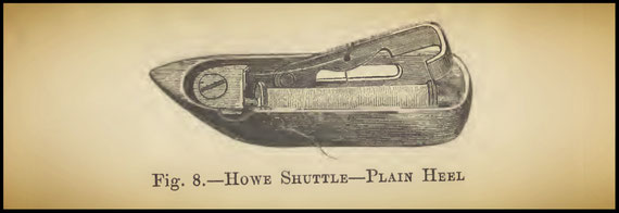
It is necessary that the needle should play as near as possible to the shuttle without touching it, and for this purpose the small cam, 27, may be turned so as to bring the needle out into the race, or cause it to recede into its groove. The actual appearance of the needle and the end of the needle bar is shown to the left of Fig. 7, where 41 is the needle-set screw, and 45 the set screw of the thread guide, 44. Fig. 8 exhibits the shuttle, without the driving heel, removed from the race, with the bobbin latch raised to admit a wound reel of the under thread.
34
From the bobbin, when in its place and the latch closed down upon it, the thread is passed into the catch cut in the latch, and from this point is threaded around and under the tension plate, and out by the hole nearest to the point. All parts of the shuttle and driver are made very smooth, so as not to chafe the thread in passing over them. The driver fits the heel of the shuttle very loosely, to allow the thread to escape easily.
35
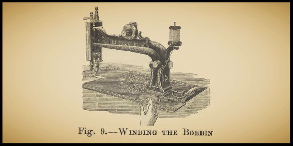
Shuttle drivers are made to act in a great many different ways, hut the result is the same. The way in which the stitch is made is explained in the Elements, at p. 20. Shuttles are made of different forms to suit the construction of the machine. They are usually of steel, highly polished. The face must be quite flat. Shuttle reels are sometimes dispensed with in Singer machines by using ready-wound "copes" of under thread. A reel 1 winder is attached to the treadle-wheel motion or table of every shuttle machine, by which the thread may bee regularly wound on the bobbins as exhibited in Fig. 9. When the bobbin does not play easily in the shuttle, its steel spindle is pointed at either end, and revolves between a spring centre and the heel of the shuttle. In the Singer machine a " loose wheel " arrangement is employed, by which the machine itself is inactive when winding the reels for bobbins. The work in most shuttle machines is fed from thes operator. Wheel feeds are common. A great number of attachments, enabling the machine to do every description of sewing, are applicable to the machine, but cannot be mentioned in detail here. The more important are Hemmers, Tuckers, Binders, Braiders, Corders, Trimmers, Kilters, and guides of various kinds.
36
CHAPTER IV
DESCRIPTIONS OF ROTATING-HOOK MACHINES
The machines introduced and manufactured by the Wheeler and Wilson Sewing Machine Company present the best examples of the rotary-hook lock-stitch type. The rotating hook has of late been applied to machines of various patterns, but the action is the same throughout.
Fig. 10 exhibits a No. 1 Wheeler and Wilson machine of approved construction for the lighter classes of work, details of which are given further on. The various parts included in this general view are indicated by numbers.
1 is the cloth plate, forming a platform upon which the work is fed under the presser foot, 2. This presser foot is provided with a glass body, through which the progress of fine stitching may be observed. The pressure is adjusted by a spiral spring upon its piston, which is fastened in position by the; thumb screw, 3. 4 is the lifting lever used when the presser is to be raised. 9 exhibits the clamp by which the curved needle is made fast to the extremity of the needle arm and through which is pierced an eyelet, 5, for the thread, as shown. 11 shows the tension pulley and 13 the volute spring.
37
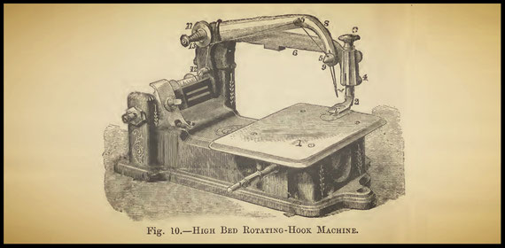
The former is a metallic wheel with a narrow groove, around which the upper thread takes one turn: the pulley is thus caused to revolve by the thread and the tension upon the latter depends upon the pressure applied to the spring, 13, by the thumb nut. 12 is a spring thread guide, through which the thread passes. It contains a pair of steel discs clamping the thread, and pressed together by a small spiral spring. Motion is communicated, from an eccentric beneath, to the needle arm through the joint, called the hinge, bolted to the rocking bar, which plays between a pair of pivots as shown. The hook spindle, 10, is used for the purpose of revolving the metallic spools for the under cotton in the operation of winding. The whole machine is built upon a firm casting, which is screwed to the table of the stand and driven from the treadle power by a strap as usual.
38
Fig. 11 is a general view of the same machine with the cloth plate removed. 3 is the leather-covered pulley, or " drum," through which motion is given to the feed hook and needle arm. 5 shows the feed frame in position in the main frame and 6 its point and teeth, which feed the cloth under the presser foot.
At 7 is a spiral spring continuously pulling the feed points towards the cam cut upon the pulley, 3.
8 its the edge of the rotating hook, in the cavity of which is devolved the under thread bobbin or spool, 1.
2 is the brush segment, the office of which is to hold a small brush loop check against the side of the revolving hook.

At 10 is shown the ring slide or " spool ring," which serves to retain the spool loosely in its place. This ring slide is adjustable, and is fastened to the frame by the set screw, 11. In the engraving before us the slide ring is of the hinged type, which is more fully illustrated by Fig. 12. The ring, a, is hinged as shown to an adjustable seat, set by the screw, c. The ring, when in position for sewing, as in Fig. 11, is retained by a snap spring, which is pressed out of action when it is required to remove the spool by a finger lever, b, Fig. 12.
39
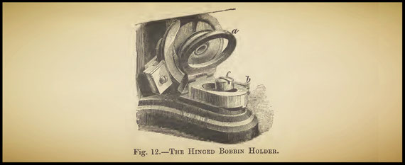
Fig. 13 exhibits the cloth plate removed and reversed.
35 shows the needle plate, through which also work the feed teeth. This small plate is removable by drawing it out longitudinally. Two sizes of needle plate are used, one for fine and the other for coarse work.
57 is a wire under which the spool thread is usually passed in commencing work, which prevents the end from getting entangled in the hook.
54 is an eccentric cam, working upon the stud, 55.
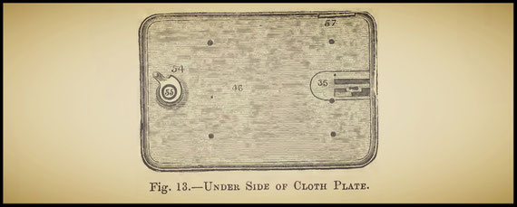
Its function is to regulate the length of the stitch by butting against the feed bar, the old style of which is shown in Figs. 14 and 15. Fig. 14 explains the under motion of the eccentric and feed cam. 8 is the eccentric band giving motion to the needle arm.
7 is the driving strap. 6 shows the feed cam, which actuates the feed bar, 10, by bearing upon the abutment, 11.
40
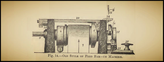
The spiral spring pressing the feed up to the cam is shown in position at 12. The feed bar works freely in seats cut in the main frame. The feed tongue, 13, Fig. 15, is hinged to the bars and works up and down freely between them.

41
The teeth are cut upon the free end, 14. This feed tongue is raised by the same cam block used for giving the feed movement, but the necessary eccentrical form is cut upon the periphery of the casting. This feed is a most ingenious one, and has four motions. First, the feed tongue rises and presses its points into the cloth, then the whole feed frame moves forward the length required, carrying the cloth with it; the tongue then drops, and the feed bar finally draws back for a fresh movement.
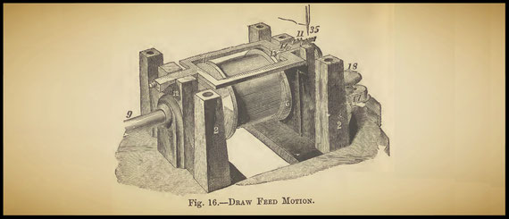
All these motions are repeated for every stitch taken by the machine. The points, 14, are hardened to withstand wear and tear. Fig. 16 illustrates the more modern feed, known as the " draw feed." In this form the frame is square, and has no drop tongue. The entire frame moves at the forward end with the four changes necessary.
42
At 12 is shown a spiral spring, which not only pulls the feed back, but tends to press its rear end upwards against the plate: at the point where the feed touches the plate we may imagine a kind of fulcrum or hinge action when the feed point is raised or depressed. At Fig. 17 is shown the feed removed from the frame. At 11 is exhibited an improved feed point of time steel, which is so made as to surround the needle and give great power and accuracy in feeding; it is screwed to the end, 14, of the feed frame by one screw. Two screws are here shown; the use of the second screw is to raise the feed point as the bearing piece, hinged below, wears away.

This form of feed bears upon the throw cam with a pad of leather to reduce noise; a similar pad is used at the regulation end of all these feeds. The motion of this " draw feed " is the same in effect as that of the bar feed. It is better adapted for feeding thin and soft goods and works with less noise. In the newer form of feed cam, as shown at 6, Fig. 16, the feed is raised, not by a cam cut at 6, but upon the hub, marked 4 in Fig. 13.
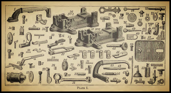
Before proceeding to an explanation of the action of this machine in making stitches, reference to Plate I. will render clear the form of the different parts of which the machine is made up.
43
The brush used in checking the loops and the action of which has yet to be explained, is shown at 3 d and its " segment," or holder, at 3 a.
At 14 is exhibited the eccentric cut upon the main pulley;
21 shows the corresponding eccentric ring and rod for transmitting motion to the needle arm, which is exhibited at 45.
The hook, 42, passes its spindle through the pulley. The thread bobbin, or spool, 4, lies in the cavity of the hook and is controlled by the slide ring, 5.
1 shows the presser arm, which is screwed firmly to the frame and through the end of which works the presser-foot piston, 54 b, actuated by the spiral spring, 56.
The hinge lever, 64, connects the end of the eccentric rood and the rocking bar of the needle arm together.
27 is the feed frame, as already described, with its point, 32, removed;
28 and 33 are the leather stops previously referred to;
30 the bearing block, against which the raising cam acts in raising the feed.
This part is hinged at the end of the feed and is adjusted by the screw, 35, while the screw, 34, serves to fasten down the point.
At 29 is exhibited the spiral spring which draws back and regulates the motion of the feed.
48 is the needle yoke, with its nut, 49; this part clamps the curved needle, 50, to the arm.
19 and 55 are the presser lifter and raising collet respectively; the collet is screwed upon the upper end of the presser spindle by the thumb screw, 57.
At 71 is shown the tension pulley, which runs upon the stud, 72.
76 is the volute spring, which is regulated by the nut, 73.
77 shows the spring thread guide, previously referred too, removed from the needle arm.
At 46 is shown the shape of the pivot or needle-arm screw, upon which the arm moves; this screw is locked in position by the lock nut, 47.
The spool wire, upon which the reel of thread is placed, is shown at 68.
44
45
The disc marked 15 screws to the end of the eccentric after it has been passed through its ring, to prevent shifting. 38 indicates the shape of the glass foot used in these machines. The various screws are also shown. Having thus far paved the way towards an intelligent understanding of the construction of these machines, we may pass on to an examination of the action of that beautiful piece of sewing mechanism, the rotating hook. Fig. 18 is a view of the face of the hook used in this form of machine.
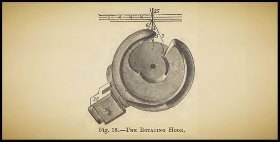
The needle is represented as passed downwards through the cloth. Let us suppose the needle to be at its highest point, and the thread placed upon the machine and passed through the needle eye, which is pierced near to its point. The disc-like spool containing the under thread is to be in position in the hook cavity, and the ring placed in front of it to keep it there, although loosely.
46
Pulling a little thread from the under spool, we move the machine slowly forward. The needle descends, carrying the upper thread with it, and passes through the cloth down to the rotating hook. After it reaches its lowest point it begins to rise again, and in doing so, the thread stretched upon its side next to. the hook point slackens and begins to form a "loop," 5, as shown in the engraving. The hook, meantime, has been revolving to meet the needle, and when the latter has risen to the extent shown, the hook point is ready to enter the loop. Further rotation causes the needle to rise, and the hook to pull out and expand upon itself the loop; in doing this it draws the left side of the loop behind the spool, and a little further motion causes the loop to slip off the hook at the chamfered portion, shown at the bottom of the engraving. The result is that the loop is now passed fully over the spool, and is pulled forward with the friction until it is checked by the brush, 3, in its holder, 36. At this point the loop remains until the hook has seized a new loop, when further rotation brings the chamfered part referred to opposite to the brush, and the loop is both relieved and drawn up into the cloth by the expansion of its successor. When the loop slips off the hook, to pass over the spool, the needle eye is just entering the cloth, so that the strain upon the upper thread is lessened at this point. The motion of the hook is accurately timed to that of the needle, and the loop referred to is always formed before the hook point moves past the needle. The under thread is, of course, caught up at each stitch by the spool being encircled, and is pulled up into the cloth to make the lock stitch. There is always a gentle tension on the under thread, due to its holder revolving in a direction opposite to the movement of the rotating hook.
47
During these motions the feed moves the cloth forward the length of one stitch at every rise of the needle. The action of the rotating hook is, practically, throwing the upper thread over the under one, which is analogous to the passage of a shuttle through the loop. The hook is made from steel and is very highly and smoothly finished off, to prevent injury to the thread by cutting or chafing.
The action of "Wilson's rotating hook is somewhat difficult to render clear by word description. The point seizes each loop with unerring accuracy at lightning speed, whirls it over the spool, leaves it upon the brush, and pulls it into the cloth with inconceivable rapidity and yet not even the finest threads are chafed or broken by it. Even at the prodigious speed of 2.500 revolutions a minute, when the time occupied in making one stitch is a mere fraction of a second, the resulting stitches are perfect and no break or miss is apparent in a run of any length.
48
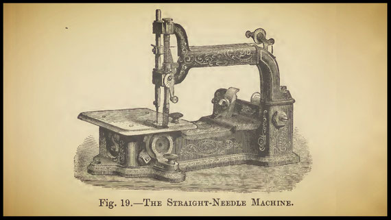
The feed likewise acts to perfection and so accurate is the stroke that all the stitches are of the same length. In the later forms of the rotating hook its cavity is made much deeper, to accommodate a wider spool containing a large supply of under thread. The brush check is also done away with in the larger machines and an automatic " take-up," to be described further on, completes one stitch before another is begun. Fig. 19 represents the same type of sewing machine, but fitted with a straight instead of a curved needle. The positions of all the parts are the same as in the machine just described, and the additions consist of a needle bar and a link to connect the needle arm to it. This machine is adapted for heavier work than the curved-needle machine of the earlier form, and serves, as it were, as a link to connect the older machines with the new types described hereafter.
49
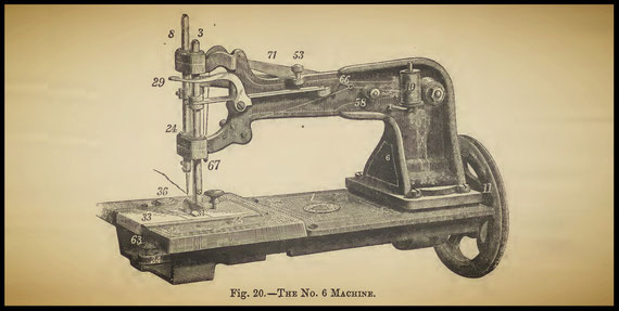
The "Wheeler and Wilson Nos. 6, 7, & 8 Machines
As these machines are all constructed upon essentially one plan, a description of No. 6 will suffice to illustrate their peculiarities of mechanism. Fig. 20 is a general view of the machine with a rolling presser foot, suitable for leather work, fitted to it. As will be at once apparent, the plan of the machine is essentially different from that of the earlier forms, giving greater strength and perfection of work upon thick and heavy materials. The pulley, 11, has two speeds, so that the machine may be driven fast or slow to suit the material: motion is communicated from this wheel to the under parts by mechanism, which will be explained at length further on. 8 shows the needle bar, which is hollow, to give lightness combined with strength. Both this bar and the presser spindle, 3, work in stuffing boxes, packed with felt washers, and provided with oil recesses. This excellent idea effectually prevents oil from running down the needle bar and soiling the goods, while it allows of the efficient lubrication of the rods, with less wear than usual. The pressure is adjustable at will by the screw, 53, and is released when required by the lifting lever, 29. The reel of upper thread is placed upon the spool pin, 10, and is carried on its way to the needle over the end of an automatic take-up lever, 71, actuated by a cam from beneath. At 31 the needle plate is screwed in position, and the plate, 33, serves to cover the working parts underneath. As in the first machine, the bobbin holder or slide ring, 34, is fixed by a thumb screw, 63.
50

51
Fig. 21 is a view of the same machine in position for working, and with its plate covers removed to show the working parts. The needle arm, 17, is pivoted to the main arm, 6, and is actuated from beneath by a cam, to be explained subsequently. It is hinged to the needle bar by a link as shown. The thread is passed from the reel under the arm, over and in the slot of the thread guide, 69; then around the tension pulley, 75; thence, leading from the top of the pulley, over the top of the controller screw and in the controlling finger; then under the thread jack wire, 67, and over the end of the take-up lever, down through the guide on the needle bar to the needle.

The controller referred to is an ingenious device of a spring and eyelet, by which any slack found upon the upper thread, when entering thin goods, may be taken up, to produce a perfectly formed stitch. By reference to Fig. 22 it will be observed that the cams which actuate the needle lever and the take-up are cut upon the same cylinder, 4, the one upon its face and the other upon its end, 73. This double cam is fixed upon the driving shaft, which is connected with the hand wheel, 11.
52

Fig. 23 will further elucidate the construction of this double cam. Between the driving shaft, 12, Fig. 24, and the hook shaft is a device for producing a variable motion, so that while the velocity of rotation of the former is uniform, the motion of the latter shall be alternately accelerated and retarded. This end is attained by the use of a circular disc, 81, revolving in a fixed yoke, 80, and eccentric to the axis of the driving and hook shafts, which lie, however, in the same line.

53
On opposite sides of the centre of this disc, and along the same diametrical line, are two slots. A pin, 35, from the flange, 82, of the driving shaft, 12, works in one of these slots, giving a variable motion to the disc, due to the latter being eccentric to the axis of the shaft. The other slot receives a pin, 36, from the flange, 15, of the hook shaft, 18, which is thus given alternately a quick and slow motion in a greater degree than the variable motion of the disc itself. The pins being at equal distances from the axis of the driving and hook shafts, the hook moves twice as fast through two thirds of its revolution as through the remaining third.

The amount of variation of motion depends, of course, upon the eccentricity of the disc, and the distances of the pins from the centres of the flanges. Fig 25 is a longitudinal section of the same ingenious motion. In the later construction of the machine this beautiful idea has been carried out in a much simpler manner, by the employment of the two discs, 82 and 15, connected together by a link, acting sometimes eccentrically and sometimes concentrically to the hook disc, the result being a hook motion which is alternately accelerated and retarded according to the position of the link pin in relation to the hook shaft.
54
This improvement is an important one, and reduces the friction to a minimum. The rotating hook, which is illustrated in Fig. 26, is of peculiar and improved construction, the tail or guard overlapping the point, so that the under thread from the bobbin cannot interfere with the loop thrown out by the needle. The cavity of the hook is very deep, so as to admit a bobbin holding much more thread than usual, and more than can be received in an ordinary shuttle.
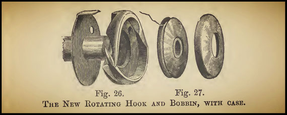
This bobbin is contained by a case, as shown, called the shield, which is open on the side next to the hook, and kept in position by the spool ring. This case permits the loop of upper thread to be carried around the lower thread without disturbing the position of the bobbin, and further prevents the loop from being cast off the hook into the wide mouth of the bobbin, instead of passing over it, Fig. 27.
55
56
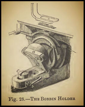
Fig. 28 exhibits a peculiar form of bobbin holder employed in some of the larger sizes of this machine. Instead of slipping the holder back, it is hinged as exhibited, and as explained at p. 40, Fig. 12. The catch spring is shown at b, where a finger lever is provided to release it when required. The forked drop piece, a, taking the place of the ring previously mentioned, is
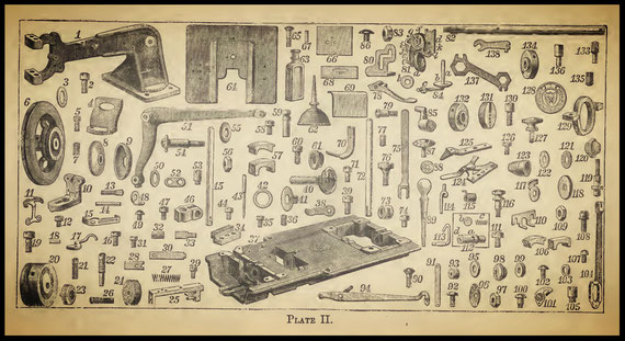
fitted with a steel spring, the face of which bears upon the bobbin case, and presses it gently into position. This bobbin holder is adjustable by means of the screw c, and may be wholly removed, without withdrawing this screw, by the expanded end of the slot, as exhibited. In Plate II. is given a complete collection of all the parts in miniature, by which the construction of this most excellent machine will be rendered still more intelligible. The machine being threaded and put in slow motion, the needle descends, carrying a bight of thread through the goods and into the cavity of the hook, the take-up lever letting down thread enough for this purpose. As the needle passes the lower dead point, and begins to rise, a loop is thrown out, which is immediately entered by the point of the hook, the under thread from the bobbin being held clear of the loop by the tail of the hook. The needle,having risen clear of the hook, pauses with its eye still below the fabric, while the take-up lever descends and gives out thread enough to complete the loop, which is expanded by the hook, and carried over the bobbin. This part of the revolution of the hook is in its faster motion. The loop having been carried around the bobbin and cast off the hook, and the needle having risen entirely out of the cloth, the take-up draws up the loop and completes the stitch. While the stitch is being drawn up, during the interval between the casting off of one loop and the entering of the next, the hook is on its slower motion.
57

At the moment of drawing up the stitch, an under tension apparatus, which is illustrated in Fig. 29, comes into play. 1 is the hook washer, also shown in Fig. 26; 2, the projecting pad, which, when in position, outlies the periphery of the hook; 4 is a plate which is screwed to the frame of the machine; 3, a perforated finger held in proper position on the plate by dowel pins, which leave it free to be lifted from the plate. The needle, at each descent, passes through the hole in the tension finger, and through it also passes the under thread. 5 is a horizontally movable lever, one extremity of which bears on the tension finger. At each revolution of the hook the pad, 2, collides with the tension finger, 3, and clamps the lower thread just as the take-up is completing the drawing up of the loop and the tightening of the stitch. The under tension is varied by moving the lever, 5, and bringing it to bear upon one or other point of the finger, and causing the latter to press more or less upon the pad.
58
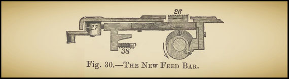
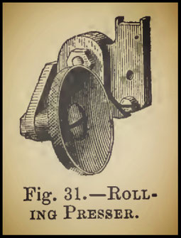
When the stitch is completed the pad moves from the finger, and entirely releases the under thread from tension. Knots or loops do not interfere with its action. By means of these most valuable improvements the stitches are produced with a uniformity and beauty of appearance scarcely to be credited. The feed used in these machines, exhibited in Fig. 30, is of the four-motion kind previously explained, but provided with an additional bearing for heavier work. The presser lever is adapted to receive flat or rolling pressers or trimmers and other attachments, and by an ingenious joint the foot may be thrown aside, to have a clear way when threading the needle, as in Fig. 31. The work is fed from the operator, but the arm may be either to the left or right, at the option of the purchaser. This machine (No. 6) is turned forward, the top of the pulley from the operator.
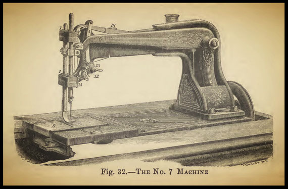
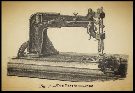
Fig. 32 is a general view of the No.7 size of Wheeler & Wilson machine. The arm is longer to accommodate heavier work, for which all the parts are specially adapted. Fig. 33 represents the same machine reversed, and with its plate covers removed to show the under parts. The arm of this machine is to the right, and its pulley is turned towards the operator, from the top. The rotary hook being precisely the same as in the No. 6 size, but lying in the opposite direction, there is necessarily a slight difference in the feeding mechanism, due to the feed cam being turned with the hook towards the operator, while the feed is constructed to act in opposite direction. This machine is also fitted with the new variable motion link, mentioned at p. 54.
59
60
61

The friction roller, which runs in the cam actuating the needle arm, is made in two parts, adjustable for wear, so that play may be taken up when required. Fig. 34 represents the No. 8 machine, which is constructed with a view to give great speed, and to run very lightly, for domestic use and the lighter kinds of manufacturing. The chief points of difference between it and the No. 6 or 7 machine are almost obvious on glancing at the engraving. The needle arm is moved by an eccentric and connecting rod. The take-up is pivoted at the base of the fixed arm, and moved by a cam, 25. The upper tension apparatus is situated above the arm, as shown. Running from the reel, the upper thread passes from the take-up over a roller attached to the fixed arm, and thence directly to the needle, the thread controller being dispensed with.
62
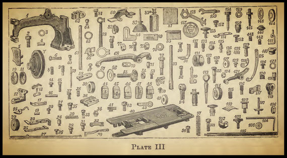
The feed mechanism is of the four-motion kind, as in the other sizes of this machine, and the hook and under spool are also the same. This size is especially suitable as a hand machine, and is light and portable. To render it suitable for this purpose, a hand wheel, gearing in a pinion upon the spindle, is fixed to the arm, and the machine is mounted in a wooden base, which, when not in use, is enclosed by a case. The stitch is regulated as to length by a thumb screw placed near to the base of the arm, as shown at 24 in Fig. 34. This screw communicates with the buttend of the feed by a rod fixed under the frame. A stitch index is provided, by which the length of stitch may be determined previous to commencing to sew. The glass presser foot is usually employed with this machine, and is capable of being drawn out when required. Plate III. contains the No. 8 machine dissected, showing the difference between its parts and those of the No. 6 and 7 types.
Instructions for using Rotating-Hook Machines. The following directions and suggestions should be carefully observed by persons desiring to operate the machines mentioned.
The Nos. 1, 2, & 3 Wheeler and Wilson Machines
To thread the Machine. Place the reel of cotton on the wire at the back of the machine. Pass the thread through the thread guide, pressing it as far back as possible, then upwards in front of the tension pulley, once round the latter, thence through the eyelets in the needle arm, and finally through the needle eye, from left to right, drawing it four or five inches to the right and back of the cloth presser.
63
64
This thread may be held loosely between the thumb and the finger. To wind the under thread, raise the cloth presser and unthread the needle; place the reel of thread upon the pin on the table, and the metallic bobbin upon the spindle ; wind the end of the thread two or three times around the inside of the metal bobbin; then work the treadle as when sewing, holding the thread between the finger and thumb to guide it into the bobbin. Use the under thread slightly finer than the upper. Put the metallic bobbin in the cavity of the hook, with the thread flowing from its top towards the front of the machine. Place at its right the slide ring upon the slide bar, close it in, and secure this part by the thumb screw. Draw the end of the lower thread forward between hook and slide ring, leave it in the thread catch, beneath the edge of the plate, until two or three stitches have been taken, and then liberate it.
To change the Needle Plate. Two needle plates are furnished, one with a small needle hole for fine work, and another with a large hole for coarse work. They are held in place by a small screw, and may be changed by removing the screw and drawing out the slide by the point on the needle wrench.
The Feed. The work is moved forward under the needle by the teeth of the feed. At each revolution of the leather-covered pulley the teeth are pushed forward above the face of the cloth plate, carrying the work ahead of the needle the distance required for each stitch. If the feed require cleaning, remove the crystal from the cloth presser, take out the feed bar, wipe all the parts clean, and set it back in position. If the teeth do not catch the cloth strongly enough, turn the screw used to raise the draw feed point (page 43) down a very little.
65
This will raise the teeth above the cloth plate. The feed points propel the fabric; the operator has only to guide it. To make a long stitch, push the lever of the feed stop from the front of the machine. To make a short stitch, draw it forward towards the front of the machine. Be careful not to pull the lever so far forward as to stop the feed bar from working.
To lace the Band. Remove the cloth plate by taking out the screws by which it is fastened to the frame. Remove also the feed frame and the bobbin. Pass the band around the band wheel below the table, through the holes in the latter, and around the leather-covered pulley below the feed bar. Cut the ends carefully, and after piercing them each with four equidistant holes, lace them with a fine cord. Draw the ends together, being careful not to overlap them, or make the belt thicker by lacing. The band having been adjusted to run pretty tightly, press down any high portions of the joint, and replace the feed bar and the feed spring. Replace also the cloth plate.
To set the Needle. Place the needle with head or shank in the needle yoke, with its eye ranging from left to right, and the curve outwards, or to the front of the machine; the flat part of the shank of the needle will then be to the left hand. Secure it by screwing up the nut to the right of the needle yoke ; for which purpose use the needle wrench. Set the needle so that in its descent it may pass through the centre of the needle hole, as close as possible to the left of the point of the rotating hook without touching it, and its eye about one-sixth of an inch below the point of the hook, or level with the edge of the shield behind the hook point, so that the point of the hook may enter the loop made on the right side of the needle as it begins to rise.
66
If set too low, the needle will scratch the hook, and its point become turned.
The Brush Loop Check. This brush should press snugly upon the circumference of the rotating hook, but not on the chamfered part. The function of this brush is to retain the upper thread until the point of the rotating hook takes the succeeding loop formed by the needle; it ought to liberate the thread when the point of the hook has fair hold of the next loop. Should this check brush become worn, so as not to check the loop of thread, adjust it with the fingers by unscrewing the brush screw. To place the Bobbin in Machines fitted with the
New Hinged Slide. Press the finger lever to the right of the slide ring, and turn back the drop. Place the bobbin upon the drop or ring with its lower edge within the cavity of the rotating hook, and the thread winding from the top of the bobbin towards you. Turn up the drop until secured by the catch.
Broken Under Thread. If the thread should break in the metallic bobbin, its end can be found with the thread hook supplied with the machine. Never use any other point for this purpose.
Regulating the Tension. The tension is regulated by turning the nut at the end of the volute spring ; a proper stitch is obtained when the upper and under threads interlock in the centre of the fabric, showing both sides of the seam alike. If the lower thread lies upon the lower surface of the work, the tension is too light; increase it by turning the nut towards you. If the work puckers, or the upper thread lies upon the upper surface of the work, the tension is too great; diminish, it by turning the nut backwards.
67
If loops occur on the under side of the work, examine the tension pulley, and see that the thread passes properly around it, and that it is not clogged by accumulation of dust or broken cotton.
To Sew. Be seated before the machine; place one or both feet upon the sandals, with the toes under the sandal straps. Start the machine by raising or depressing the toes; or, if necessary, turn the balance wheel with the hand upwards to assist ; never turn backwards, but move the hand always in the direction indicated by the arrow at Fig. 14. In sewing keep gentle hold upon the free ends of the threads until a few stitches have been taken.
To Gather. Make a long stitch with loose tension, relax the tension by turning the nut at the end of the volute spring from you, so that the lower thread will not be drawn into the fabric, but be upon the lower surface. Gather by drawing up the lower thread, which should be a size or two coarser than the upper thread. When stitching fabrics to be gathered, place the right side of the material downwards.
The Large Gauge. This gauge is used for wide tucking, quilting, and plaiting shirt bosoms. It is fastened by the thumb screw to the under side of the stationary arm, and can be moved forward or backwards, according to the width of tuck or plait desired. To adjust the same gauge for quilting, loosen the screw which connects its parts, and raise the lower part to allow the goods to pass between it and the cloth plate; then tighten the screw. The last seam sewn should pass directly under the gauge, and the next seam will be parallel to it.
68
The Plate Gauge. This gauge, for sewing close to an edge, or for tucking, is attached to the cloth plate at the same hole, using the thumb screw. For very narrow tucks the plain crystal must be removed, and the one with the side cut away placed in its stead. The two gauges are not used in conjunction.
To adjust the Old Style Hemmer. Loosen the fixed arm by starting out the screw by which it is fastened to the standard. Remove the cloth presser by unscrewing the screw. Put the hemmer in place of the cloth presser. Secure it by the thumb screw, and fasten the arm to the standard, as before.
To adjust the New Style Hemmer. Remove the crystal from the cloth presser with the point on the small end of the needle wrench, and substitute the hemmer.
To change the Spiral Spring. Remove the presser by unscrewing the fixed arm; unscrew, draw out, then place the spiral spring round the presser, and readjust.
To Hem with the Hemmer. To make a narrow hem, roll the corner of the cloth slightly, enter it in the convolution of the hemmer, and draw it along to the needle. The hem is then turned, and stitched as in ordinary sewing. To make a wide hem, fold the cloth the width of the hem, and pass the edge through the hemmer. Use the light cloth presser spring for hemming and light work. If the needle is bent so that it does not catch the edge of the hem, spring it a little to make it descend in the proper place.
To Fell with the Hemmer. Join the two edges of the fabric together as if it were going to be felled by hand, leaving the edge that is to be turned down the width of this line (—); then open out the fabric, put the widest edge into the hemmer, and proceed to sew. Be careful that the edge is even, and of the proper distance to produce a neat fell.
69
Braiding with the Machine. "Wind the braid upon an ordinary reel without twisting it. Attach the arm for holding the braiding reel by the thumb screw to the fixed arm of the machine, in a position to bring the reel containing the braid directly over the needle hole in crystal. Insert the two-hole crystal, pass the end of the braid from the reel through the hole in the crystal, bringing it under the point of the needle, and proceed as in ordinary stitching. The Thread Oiler.—The oiler is a useful contrivance for lubricating linen threads, and it may be used when stitching dressed calicoes. Attach by slipping it on the needle arm at the smaller part, and slide it up towards the tension. Saturate the sponge with oil, place the upper thread in the slit, and proceed to sew. Emery Stone for
Sharpening Needles. To sharpen needles when their points are dulled or turned, place the circular hone on the spindle, and work the treadle as in filling metal bobbins; place the point of the needle slantingly against the hone, turning the needle with the thumb and fingers as the point requires.
To set the Needle in No. 4 Machine. Raise the needle bar to its highest point, loosen the set screw at its lower end, push the needle into the socket as far as it will go, with the long groove to the left, and secure it by turning the set screw.
To thread up No. 4 Machine. Pass the thread through the thread guide, once round the tension pulley, thence through the thread leader, the small eyelet at the end of the needle bar, and the eye of needle, and finally draw it through four or five inches to the right. In all other respects follow the instructions herein given for No. 1, 2, and 3 machines.
70
Cleaning and Oiling. Remove the cloth plate and clean well about the rotating nook, the feed bar, and the feed points. Put a drop of oil on each of the following points: the hole in arbor, at each bearing in each standard, upon the cam, the hole in the eccentric ring, also the bearing of the feed bar, and on the top of the same, the pivots at each end of the rocking bar and the hinge, and occasionally on the top of the cloth presser piston where it passes through the fixed arm, and on the bearings under the table. Use sperm oil thinned with paraffine or petroleum.
General Directions. Set the needle properly. Keep the machine clean and well oiled, and the brush check in proper order, according to directions. If the upper; thread should break, it is probably owing to one of three causes: 1st, the tension, or friction, is too great upon the upper thread; 2nd, the loop check does not press the hook sufficiently to restrain the loop which is passing over the lower spool until the point of the hook takes hold of the succeeding loop at the needle; 3rd, the metallic bobbin has become roughened on the edge, and wears off the thread in passing over it. If the thread should hang in loops on the under side of the work, increase the tension on the upper thread sufficiently to draw the lower thread up into the goods, and see that the thread passes properly around the tension pulley. Should the thread break by increasing the tension on the upper thread, and still not make a perfect stitch on the under side, examine the metallic bobbin, and see if there is any roughness on it or on the hook, so as to prevent the thread from passing freely over it. Also be careful not to break the cotton in the tension pulley, or allow it to become clogged with dirt.
71
Gibbs's Rotating-Hook Lock-Stitch Machine
This machine bears a certain resemblance in its lock-stitch mechanism to the "Wheeler and Wilson type, but the hook has also some of the peculiarities of the Willcox and Gibbs single-thread looper. In general appearance the machine resembles the single-thread machine, but the bed is larger and gives more cloth space. The improved hook invented by Mr. Gibbs is designed to be rigidly mounted upon a revolving shaft, for which purpose it is provided with a central stem which can be inserted and fixed in the end of the shaft. It is a bobbin embodying a hook; that is to say, one formed as is usual in rotating-hook lock-stitch machines, with a recess in one face to receive the bobbin. It is characterized by a certain form of construction, whereby the loop taken by it from the needle is carried over the face and rear of the body of the hook. The position to which the loop is carried by the hook as it rotates is one diametrically, or nearly so, across the body in front and rear of the latter, which position the loop maintains until released by and upon completion of the revolution of the hook. The body of the hook consists of a segment, one extremity of which forms the hook proper, and between this and the heel or opposite end of the body of the hook is cut away or recessed nearly down to the central stem, so as to form a flat edge or surface. Upon the rear side of the hook is formed an inclined surface which leads to an undercut groove or notch formed in the body of the hook, and extending radially, or thereabouts, from the centre of the stem to the circumference of the hook.
72
In this groove the portion of the loop which is on the rear of the hook is retained until it is released from the hook. The improved bobbin holder intended to work in conjunction with this hook is pivoted, and capable of oscillating on the pivot in a plane parallel with the face of the bobbin; it is also capable of moving bodily in a direction at right angles with its plane of oscillation. The former movement is for the purpose of bringing it in front of the bobbin when required; the latter, for causing it to press towards, or retire from, the bobbin. In a further development of this device, an arrangement is adopted by which tension can be put upon the under thread while the machine is in motion by means of an external independent yielding presser, which bears with more or less force upon the bobbin case. A take-up arm, having a length equal to that of the needle arm, is also employed, and is actuated by an eccentric upon the main shaft. The feed mechanism in this machine consists of a rocking shaft, actuated by an eccentric, which carries the power for the feed point under the bed of the machine. The feed itself is of the usual form, working upwards and forwards against the antagonistic spring. The upper tension has the intermittent motion given to it by a lever on the main shaft, by which means it clamps the thread firmly and keeps it rigid until released when the needle approaches the upper extremity of its stroke. This arrangement is, however, more fully described at p. 80, in the particulars given of the Willcox and Gibbs single-thread machine.
73
CHAPTER V
SINGLE THREAD SEWING MACHINES
The so-called single-thread or loop chain stitch is formed by throwing one bight of thread over another in succession, the result being the well-known chain of loops produced by various hand needles. All single-thread machines make this stitch, but in some forms of the manipulative mechanism the loops are so twisted that the result is a seam of singular utility in many classes of work, possessing great elasticity, strength, and beauty, with the additional advantage that it can be withdrawn from the fabric when required, without injury to thread or material. A simple form of looper for making the chain stitch consists of a hook, which enters the bight of thread carried through the cloth by the needle, and so spreads it out in the path of the needle, that at the succeeding descent the bight of thread is caught by the hook through the first loop, while the latter is being pulled up into the cloth. Thus one loop is thrown over its successor, to form a line of stitching which is plain on the upper side and chained beneath the fabric. The required tightness is obtained by putting a certain amount of strain on the thread.
74
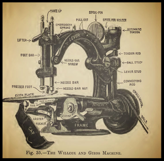
Sometimes this tension is obtained by fixing the thread reel between a pair of adjustable cones, which are prevented from revolving too freely by an antagonistic spring. The form of looper and the tension arrangement spoken of are embodied in the single-thread machine of James Weir.
The machine invented by James E. A. Gibbs, which is now the special manufacture of the Willcox & Gibbs Sewing Machine Company, claims attention as a beautiful development of the first crude ideas in chainstitch machine construction. Fig. 35 is a general view of this machine, with the later improvements.
75
The driving power is taken from the small hand wheel, driven by a band as usual, through a shaft under the cloth plate to the feeder and rotating hook, the form of which, with its point advancing to the needle, is shown under the cloth plate. This Rotating Hook is of peculiar shape, and twists the loops in a fashion which gives to the Willcox and Gibbs machine its well-known superiority. When the loop is seized, the needle begins to ascend, and, as the hook continues its revolution, the loop is twisted once across the path of the needle—that is to say, the front part of the loop is turned to the back, and vice versa. The loop is now held spread out under the needle hole until the needle descends and the hook is enabled to catch another loop, which is twisted similarly to the former one. The hook, by expanding out loop No. 2, assists in pulling loop No. 1 into the cloth. Gibbs's looper is made in hardened steel, and is highly polished at every part. It is provided with a stem, which, as it fits and is screwed into a hole in the extremity of the shaft, permits of the hook being easily set in time in relation to the motions of the needle. The Feeder is provided with three sets of teeth, cut in its feeding tongue, as shown. An eccentric is cut on the end of the horizontal shaft immediately behind the hook itself, and from this eccentric or cam the feed is caused to give four motions at each stitch. The feed teeth first rise into the cloth, and, to give the required displacement of the fabric, move forward under the pressure of the foot, as shown; the feed point then falls and returns to its first position, completing the four motions.
76
In the improved spring feed bar, which is shown in Fig. 35, the yielding pressure contact with the single eccentric, which produces both the vertical and horizontal movements of the feed bar, is maintained during both the up and down and back and forth movements of the teeth. The eccentric imparts to the spring feed bar, by direct contact with it, the up and down motion, whilst a link connected at one end with the feed bar at a point below its axis of vibration, and at the other with the stitch-regulating cam, bearing with yielding pressure on an upright rocker or vibrating arm operated by the eccentric before mentioned, imparts the back and forth motion to the feed bar, so that the feed is quite noiseless at all adjustments of the stitch regulating cam shown. That portion of the upright rocker or vibrating arm which is in contact with the eccentric is bevelled, or equivalently inclined, so that the feeding surface may continue its forward movement until after it shall have receded below the plate out of contact with the cloth. The proper adjustment of the feeding surface in the cloth plate is effected by making the bearing screw or pin of the link, which acts as the upright rocker, adjustable in the link, and the stitch-regulating cam is connected by a pin with the grooved end of the link, so as to cause the latter to rise or fall when the cam is adjusted, and then bear on the rocker at the proper distance from the centre of oscillation of the latter, according to the length of stitch required. The groove or slot in the end of the link, in which the pin of the stitch regulator works, is of a curvilinear form, so that the portion of the slot which has its play on the cam pin shall be parallel with the cloth plate, or nearly so, at all positions of the cam.
77
The stitch-regulating cam is provided on its concentric peripheral portion, on the upper half, with certain figures, indicating the number of stitches to an inch, and is arranged so as to present the portion mentioned tangentially to the cloth plate, so that the number which is upon the tangential portion of the cam may show through an opening made for that purpose in the cloth plate, as exhibited in Fig. 36, which is a view of part of the cloth plate. To the right is stamped a useful table for the guidance of the operator in the selection of the most suitable sizes of needles and threads. Referring again to Fig. 35, a stop pin is fixed into the frame of the machine in order to limit the play or movement of the stitch-regulating cam within the compass of the series of numbers on the periphery of the cam. This pin engages in a curved slot or recess in the cam. Passing upwards to the cloth plate itself, three slots are cut through the plate, in which work the serrated surfaces of the feed, which is so formed as to almost surround the needle hole. In addition to this, the upper surface of the cloth plate, in the immediate neighbourhood of the feed space, is serrated, so that the cloth may be prevented by the forward-set teeth from receding from under the bevelled end of the foot when the feed releases its hold on the cloth. This device greatly facilitates the operation of feeding seams or thick portions of the cloth through the machine. The needle hole is elongated, a form found to be best suited to the formation of a good loop stitch. In addition to the plate being serrated on its upper surface, it has been found advantageous to cut teeth also on the under side, immediately over the feed points; by this means the fluff or other offcast from the fabric or thread, which often chokes up the feed teeth and stem, is worked off the plate and thrown into the cap, shown in Fig. 35.
78
The cloth plate is screwed to the frame, and is easily movable for the purpose of cleaning. The Needle Arm is jointed to the frame by the lever stud (Fig. 35), and is free to move thereon in a vertical arc. Its short end, to the right of the stud, is grasped by a joint, working upon a ball stud. The motion is taken from the horizontal shaft by an eccentric, the periphery of which, with its bearing on the collar, is ball-shaped to increase the wearing surfaces. One revolution of the hand wheel thus causes the needle arm to vibrate once in both directions. The arm is jointed to the needle bar by a ball joint of ingenious construction, providing a large wearing surface. The Needle Bar moves vertically in two bearings drilled in the standard. Upon its lower end it carries a needle-clamping screw, which, when screwed upon the tapering or split extremity of the bar, closes the two spring sides upon the needle. In addition to this the needle is grooved on its shank or stem, which groove, corresponding with a steel tongue or plate within the needle holder, insures the correct setting of the needle. This will be further explained. At its upper end the needle bar carries a double loop of steel, working in proximity to an upright square-section stud. The whole arrangement constitutes the thread take-up, the function of which is to pull the stitches tightly into the cloth at the required moment. The action of the take-up detains the descending thread, which is passed through the metallic loop, until the eye of the needle is on the point of entering the fabric.
79
The Presser Bar is likewise carried by the end of the standard arm, and is provided with a spiral spring continually urging it downwards upon the cloth plate. Upon its lower end it carries the presser foot, which is slotted out to permit the needle to pass, and presses the cloth upon the plate to allow of the correct action of the feed teeth. An improved foot of this description is jointed near to the end of the bar, and is kept in the position represented in Fig. 35 by a small spring. This device assists the feeding of materials of varying thicknesses into the machine, and the passage of high seams. In order to prevent the presser bar from swerving, a feather was formerly fixed to it, working in a slot in the casting, but in the improved machine this is replaced by a stronger arrangement, consisting of a second rod, working in a recess between the needle and presser bar, and made fast to the latter by a screw working through a slot. The presser lifter consists of a steel cam, provided with a handle, as shown. It is screwed or jointed to the bar.
The Thread Eyelets are fastened in the frame, and are of hardened steel. At the part of the needle arm marked "Pull-off" is a device for taking from the thread spool the required length of thread for each stitch. It consists of two stout steel wire loops, one of which is fastened to the frame or main arm, while the other is fixed in, and vibrates with, the needle arm. The action of the pull-off will be further explained in continuance.
The Automatic Tension. This most ingenious device consists of an arrangement by means of which the thread is so controlled in its passage to the needle that no adjustable tension is required.
80
The device, which is very compact, is contained in the round casting marked " Automatic Tension " and consists of a thread rest or support, upon which the thread in its passage to the needle is held by a smooth surface ring resting upon the thread by gravity simply, so as to exercise a gentle but continuous pressure thereon, in combination with a thread -clamping device, consisting of a stationary support for the thread, and a movable clamping surface, actuated by a spring, for the purpose of firmly holding the thread until the loop is almost or quite drawn up to the cloth, and then suddenly releasing the thread, leaving only a nominal friction upon it. The releasing or relieving device consists of an eccentric operating upon the movable clamping surface at the required intervals so as to release the pressure upon the thread. A washer of soft felt is interposed between the thread-holding rest and its support," for the purpose of preventing the jars which attend the action of the eccentric through the connecting rod. In order to obviate the use of oil, and therefore to render access to the interior for this purpose unnecessary, washers of leather are fixed upon the movable clamping device, serving to keep the spindle itself clear of the metallic sides of the tube or recess. An adjustable head or tappet is fitted into the upper end of the connecting rod which raises the tension spindle. This tappet moves to and from the end of the tension spindle inside the tube, and is provided at its upper end with a leather washer fitting the tube, so as to form a guide for the upper end of the connecting rod. Sound- deadening washers of soft felt or wool are interposed between the head of the spindle, spiral spring, and clamping plate
81
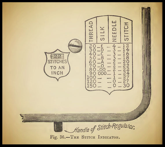
The Spool Holder. This is a device for receiving the spool of thread, and is arranged with its axis in line with the first or nearest thread-receiving eyelet, in place of being vertical as usual: it is provided at its lower end with a plate or disc, against which the spool rests. This inclined spool pin is fitted into a bracket, in which it is held at one end, so that it may be removed from or replaced in the holder at pleasure. The spool plate or disc before referred to is provided with an annular flange arranged to overhang that end of the spool which is in contact with, or nearest to, the disc, by which means the thread is prevented from slipping off the spool, and is also unwound without causing the spool to revolve as usual.
82
The obvious advantages of this ingenious device are that there is no tendency to wind the thread around the spool pin when glazed thread is in use and that the tension of the thread spool upon the thread is always equal; the machine may also be turned in any position without the usual inconvenience of the spool dropping off its pin. The Frame is, as shown in Fig. 35, substantially one casting. The cloth plate, upon which is indicated the number of stitches to the inch, is exhibited, as before mentioned, in Fig. 36.

83
Fig. 37 is a view of tho machine with the new feed movements from beneath, exhibiting the bearings and relations of the pirts, and also the various oil holes for the lubrication of the feed mechanism and main shaft. A cast-iron cap is jointed so as to cover over these parts. Fig. 38 exhibits the necessary lubricating points in the machine when placed in working position upon the table.

These points are the needle bar (two places), foot bar (two places), needle-bar screw, lever stud, shaft, lower end of tension rod, and both ends of main connecting rod.
The Needle. The short groove of the needle must be set towards the point of the Gibbs's looper and to insure this, and also the correct height of the needle, the stem or shank is grooved deeply in one side only, while the length of the shank is adjusted so that its upper end should pass as far upwards as possible into the needle bar.
84
The groove corresponds with a steel tongue in the needle-bar hole, so that the needle cannot be set otherwise than accurately. Figs. 39, 40, and 41 exhibit the operation of setting the needle in this machine. Fig. 39 shows how the point must at first be entered downwards in the needle hole to get the shank to enter the bar.
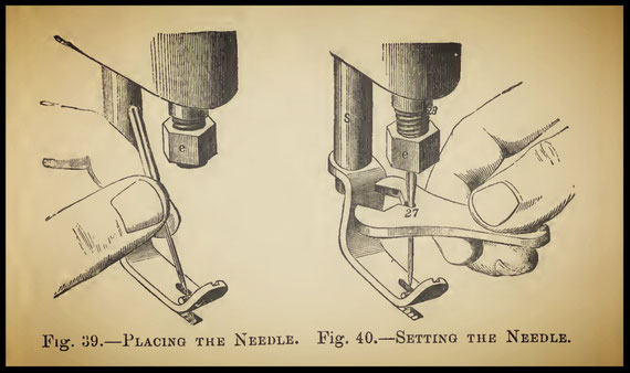
Fig. 40 renders plain the pushing up of the needle into its place by means of the setting wrench. The needle is finally fastened by screwing up the nut, which, by means of the split needle bar, causes it to be grasped tightly in position, as in Fig. 41.
Fig. 42 is intended to represent the course of the thread from the spool pin to the needle eye. The direction of the thread is indicated by the arrows. The spool pin is first pulled out, and the reel placed upon it.
85
The pin is then replaced, and the needle bar raised to the highest point by turning the hand wheel. The course of the thread from the spool is, first from the back towards the operator, through the two staples and the arm known as the pull- off (Fig. 35), when it is passed once around the automatic tension, marked 2, Fig. 42 and from this point to 3, the eyelet on the arm, thence to the loop marked 4, through the take-up loop, 5, and the eyelet, 6, and finally into the needle's eye.
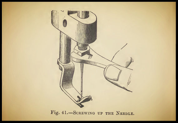
The machine is now ready for working. The fabric, as in most other machines, is fed from the operator. No regulation of tension is necessary. When the work to be sewn is extra thick, or when sewing on braid or cord, the thread is passed through the embroidery spring also, which is shown in Fig. 35.
86
For such classes of work as require to be turned continuously, such as straw hats, the machine is fitted with a "vibrating presser," which is actuated so as to rise off the work to the required height at each stitch, to facilitate the operation of turning the goods with ease. This attachment may be put in and out of action at pleasure.
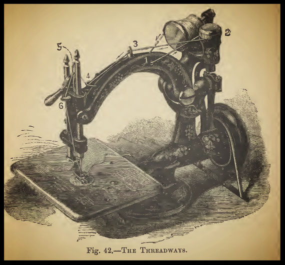
The New Straw Hat Machine embodies all the peculiarities of the recognised Willcox and Gibbs's type with extra arrangements, by which the operation of sewing up a straw hat from the plait may be carried out with ease and certainty. In the first forms of this machine it was fitted with two or more feed tongues, capable of receiving different lengths of play in feeding the fabric.
87
By these means the circular straw-hat disc, by being fed faster at the outer edge than at the inner circle, might to a certain extent be caused to revolve under the needle without aid from the operator. Further experience, however, led Mr. Charles Willcox to devise a machine having one feeding surface only, with other attachments to facilitate the laying of the plait in correct position. The new feed mechanism is so arranged as to have great strength, and also to be entirely out of the path of the work being sewn. The feed mechanism is different from that applied to the common machine. A shaft some five inches in length is mounted in long bearings behind the frame, and from this shaft as an axis work the actuating arm and the feed surface itself. The former part is caused to vibrate by an eccentric placed upon the main revolving shaft, and from the arm connecting the eccentric with the back axis shaft is taken the feed-point lever. Thus the feeding mechanism is entirely disconnected from the front or hook face of the machine. The ordinary cloth plate is necessarily dispensed with, and a curved plate of small size takes its place over the rotating hook. An effective guide for the work is provided to the right of the needle plate, and is adjustable back and forth by a rack and pinion, to facilitate the changing of the width when the machine is in motion. The presser foot carries several extra attachments made in two pieces, to render the operation of making a straw hat easy and certain.
88
At this point the width and thickness of the plait or braid can be quickly adjusted for, and the "fulness" required in some work can in this form of the machine be given with greater nicety by the fingers than by a second or third feeder, as in the first-mentioned type of straw-hat machine. A presser vibrator completes the more remarkable arrangements in this new machine, which altogether should greatly cheapen the production of all kinds of straw hats.
Speed of these Machines. The rate of rotation in the Willcox and Gibbs machine is, or may be, enormous. For manufacturing purposes steam power is usually employed, when the speed of working is very great: 3.000 stitches per minute are often attained, while by foot 1.500 may probably be given. The work is done with equal perfection at all speeds.
Noiselessness in Working. The noise has been reduced to a minimum by the peculiar arrangement of the parts. Much attention has been given to this point in the Willcox and Gibbs machine, the result being an almost silent action at all speeds.
89
CHAPTER VI
PROPORTIONS OF NEEDLES AND THREAD TO WORK
The following tables are intended to serve as a guide to the sizes of needles and threads which should be used when sewing the different classes of goods indicated, so as to provide against accidents to the machines and work, and to produce the best stitching. The rules refer to three kinds of sewing machines, shuttle, rotating-hook lock-stitch, and single-thread, or Howe, Wheeler and Wilson, and Willcox and Gibbs. When the under thread is not specified to be finer than the upper, the same sizes should be used for both. When a face stitch for leather is required, the flat pointed needle is used ; and when the stitch is to be sunk into the leather the twist point is usually employed. The round common point is always used for cloth goods. The needles for all sewing machines are numbered on the shanks. Bad or uneven threads should be avoided, especially those of varying thicknesses.
90
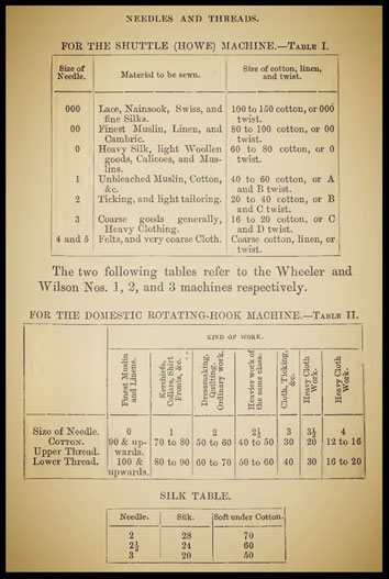
91
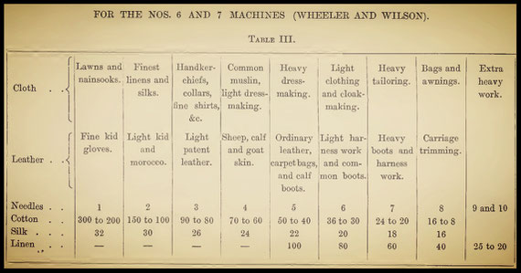
92
NEEDLES AND THREADS
The following table relates to the single-thread or chain-stitch type of machine, which is more especially adapted for the lighter kinds of work at high speeds.
TABLE FOR THE WILLCOX AND GIBBS MACHINE
Table IV
For calico, long-cloth, &c.......................................Use cotton Nos. 60 to 80
For fine lawn, nainsooks, &c........................................................100 to 150
For fine linens.............................................................................80 to 120
For light woollens........................................................................40 to 60
For heavy woollens......................................................................20 to 40
The sizes of needles to be used upon these goods are stamped upon the cloth plate, as exhibited at page 82, Fig. 36. Glace cottons work much more satisfactorily on the Willcox machine than those with a soft finish. The following statement refers to the speeds at which ordinary machines may be advantageously driven. As a general rule, the stouter the needle and the coarser the thread, the slower should the speed be. Some kinds of leather may be worked at a high speed.
SPEEDS AT WHICH LOCK-STITCH MACHINES MAY BE DRIVEN
Table V
Kind of Work Revolutions per minute
(number of Stitches)
Heaviest leather goods.....................................................220 to 250
Heaviest cloth goods.....................................................250 to 350
Medium work goods.....................................................350 to 400
Calico and finest goods.....................................................600 to 1000
93
SECTION II
DIRECTIONS FOR ADJUSTING THE VARIOUS TYPES OF SEWING MACHINERY
CHAPTER VII
THE ADJUSTING OF WHEELER AND WILSON MACHINES
To "Take Down" the Machine, No. 1, 2, or 3. By reference to p. 37, where the positions of the various sections in the smaller type of Wheeler and Wilson are explained, the allusions to names of parts following will be the more intelligible. It is a common practice with sewing-machine mechanics to attempt the efficient repairing of hook machines without removing all the parts. This is a mistake. It is usually very much easier to pull the machine to pieces at once, and to treat each part separately. A worn or badly used rotating hook cannot by any process or expenditure of care be efficiently repaired unless it be removed from the machine. In many cases the " time " of the hook is materially altered by filing and smoothing out rough places, and its removal from its bearings is then imperative. Before proceeding to take the machine to pieces, always remove the needle from its yoke; this will obviate subsequent trouble with the needle point.
94
With a large screw-driver draw the screw fastening the presser arm in position, and remove the arm itself. Take off the cloth plate, and remove the feed bar and spool ring. Cut the fastenings of the belt, and draw the two set screws let through the leather covered pulley, which hold the hook in position. The hook itself, if the machine be old and clogged with oil, may at first cause some trouble to pull out, but a little paraffin oil, with a tap or two upon the spindle end with a mallet, will usually suffice to render its removal easy. When the machine is very much clogged, and the hook refuses to draw, the paraffin oil may be left to soak in, and its dissolving and softening action may be hastened by gently heating the base of the machine. A hexagon wrench is usually supplied with the machine, by means of which the lock nuts on the pivot screws may be unscrewed. Both pivot screws should be removed from the casting. The needle arm is now free. The hinge bar, in which the eccentric rod is jointed, is next to be removed from the rocking bar by drawing its screw, and it will be as well for a beginner to mark the position of the bar with regard to the screw for future adjustment. To remove the eccentric from the pulley, draw the screw holding the check disc at one end, and the drum and eccentric may be separated. If there should be any binding at this latter point, a turn backwards of the eccentric-strap screw will loosen it. Mark the position of the check-brush holder and remove the brush and holder from the frame.
95
To Clean the Parts. Clogged and gummed oil is troublesome to remove, so that paraffin oil should be freely used upon all the parts. After a few hours the various portions may be easily wiped clean. Care must be taken to thoroughly clean out all oil ways with a metal pin.
The Spring Thread Guide. The top thread, after leaving the bobbin, passes to the under side of the spring or barrel thread guide. In this guide it moves between two steel discs, which exert a gentle pressure upon it by means of a small brass spring in the guide pressing the discs together. This guide acts a very important part in the working of the machine, its office being to hold the thread sufficiently tight upon the tension pulley to cause it to revolve. Without this spring guide, or something equivalent, the tension pulley would not revolve at all. If the tension be tight, there is all the more need for an efficient check at the first guide. In course of time and working the spring guide gets out of order by clogged oil or accumulated masses of fluff keeping the discs apart and preventing a check upon the thread. In some cases, where the discs chance to be too soft, the continual friction cuts grooves in them, and they will often fail to check fine sizes of cotton. To put this part in working order, draw the screw in the end of the guide, and carefully remove the brass spring, a bent pin will prove useful for this purpose. In most cases the steel discs will be found firmly gummed into the guide, and paraffin must be dropped into the aperture to release, them; a sharp pointed wire will assist in loosening them, and sometimes a small bar magnet is useful. When the discs are removed, clean out the socket thoroughly and dry off all oil.
96
Polish up the exterior for appearance' sake and file the discs flat upon each face, in doing which rub them with the finger upon a fine file. They should be well polished, so that no chafing of thread may take place between them. Clean the spiral spring also and replace the discs carefully, with their smoothed faces together; put in also the spring, after it the screw, and finally test the holding power of the guide by passing cotton as fine as No. 90 through it. A gentle and regular tension should be kept upon the thread.
The Tension Arrangement. A thumb nut, volute spring, iron washer, felt washer, steel pulley and another felt washer, all mounted in the above order on a stud on the needle arm, constitute the tension apparatus in this type of machine. Some machinists have a bad habit of dropping oil upon the tension, as it is commonly called, which gradually clogs it up and stops its working by hardening the felt washers. Chiefly from this cause, but partly from dust and bad usage, the tension pulley becomes clogged up, and refuses to turn regularly or to hold the thread effectually. Remove the thumb nut, spring, washers, and pulley. Drop paraffin oil upon the volute spring, and press its ends together to squeeze out all dust and make the spring work freely. The pulley must be examined in its groove, which often gets filled up with fluff, and cleaned out; for which purpose a hooked iron wire, filed very thin at the end, will be useful. The felt washers should be renewed. The thumb screws for increasing the pressure on the pulley in the old style of machine often get loose and fail to keep their position when the machine is in rapid motion. In the new machines a better plan is adopted: the nuts are split half through with a fine saw and grip the screwed spindle with a spring pressure.
97
The old style of nut may be made good by slitting with a watchmaker's frame saw, pressing together slightly while red hot, and cooling in water. It is of importance that the iron washer does not rotate upon the stud. The tension pulley must be made to run very smoothly, as any jerking will cause uneven and bad stitching. The thread must catch in the groove, and must not slip past without taking the wheel round. After turning once round the pulley, passing to the under side of the groove first, the thread passes through an eyelet in the needle arm near the bend. The thread hole in this eyelet is very frequently cut by the friction of the passing thread, and in these cuts the thread often sticks. If not of great depth the cut can be obliterated and the hole smoothed over with a fine round file. If the cut be deep, it will usually be best to turn the eyelet upside down, smoothing out the hole. From this point the thread passes downwards through the end of the needle yoke. The hole in this must be filed out and smoothed over if necessary. For smoothing out the eyelet holes a thin strip of FF emery cloth, oiled, or a piece of twine dipped in emery powder, may be used. It will be necessary to again refer to the needle yoke, to ascertain whether it holds the needle in line, but for the present the adjuster cannot go farther with this part.
The Presser Foot. In holding the fabric as we operate the sewing machine, we do so with a hand that can hardly be said to be steady; our hold is an elastic one, giving and taking as the feed moves. It will be plain, therefore, that if the presser foot or feed be not perfectly steady in its movements our work cannot be sewn in a straight line.
98
The presser foot shakes from side to side, let it be ever so little; we are stitching, for example, on the extreme edge of some linen fabric; we endeavour to make the line straight, but find great difficulty in preventing the needle from slipping too far in, or right over the edge; we naturally look to the feed for the important defect, but find it quite steady; we examine the presser, and find that it has a little play, herein lies the cause of the difficulty. If the presser foot shake, we should turn out a seam corresponding in crookedness to the extent of its play. Hence it is of much importance to fit the presser foot so that it may be as free from play as possible. The cross strips, which prevent the foot from turning round, get worn ; so does the slot in which they work, but the strips suffer most. Leaving the foot in position in the arm, fasten the latter in the vice, and measure the extent of play the foot has from side to side. This is easily done with the compass points. If the play should be very great, new strips must be put in; but if it does not exceed 1/16 th of an inch, the old ones may be made to serve. Heat the end of the cross strip in the gas, after removing the foot and having made its opposite end fast in the vice, beat it out at the extreme end so as to widen its body. The same should be done with the other extremity. A smooth file is now brought into requisition and the width of the strips reduced a little. Do not, however, yet proceed to fit the foot in position until an examination of the slots in the arm is made. A thin ward file should be used to render the sides of the guide slots parallel, and the foot may then be fitted to them. Much care should be taken to get as wide a bearing surface as possible, and that the strips may each fit its slot equally well.
99
It is usually best to fit the ends to the slots from the outside first and then to place the foot spindle in position in the arm for final fitting. The result should be that the foot should move in position with perfect freedom and yet he free from play. There is no remedy for a worn spindle except a new one, but it is rarely that the mechanic meets with a spindle so much too small as to need replacing. In fitting a new steadying pin it is always best to make it from good steel, and to polish the filed sides where they bear upon the guide slot. The slots should also be made smooth. The foot is apt to be displaced from its old position in refitting it, and it is usually a saving of time to fit the needle arm, with a needle in the yoke, in position for a trial to find whether the hole in the foot is correct. The needle plate may, however, be put in position, and this will serve to indicate whether the foot is correctly placed. In the old style of Wheeler and Wilson machine the foot itself is of steel, being bent round in one piece, rendering the glass foot unnecessary. After use the steel foot is often much cut up around the hole and on its under side, by carelessness in not raising the foot while winding spools. The hole must be filed smooth and finished off to leave no sharp projections. The under side usually exhibits two grooves, worn there by the feed teeth. These prevent the seam from turning and must be filed out, and the foot finished off smooth. It is an improvement to make such pressers hard, so that they may not be so readily acted upon by needles and feed. The foot is, however, soldered to the stem and it is difficult to harden it without loosening the joint. The foot may be made red hot quickly in a gas flame, or by a blowpipe, and the joint may easily be kept from running by covering it with wet clay or a damp cloth. While at red heat dip quickly in cold water, which should make the steel hard, too hard for working.
100
To temper the foot, polish it with emery cloth and heat gradually until a deep straw colour is apparent, cool out again and polish up. Pressers treated in this way will stand for many years. When a difficulty is met with by the foot cutting the upper thread, much care should be taken to bevel off the under side of the hole, more especially that to which the thread inclines when drawing up the stitch. Glass feet often fail to fit well in the sockets. It is usual, when they are too long or wide, to grind them down to the size. The under side of the hole through the glass must be carefully bevelled off; for which purpose a centre punch with paraffin oil or turpentine should be employed, rotating the point until the edges are ground off. If the glass foot be cracked it is false economy to use it, more especially if the crack be on the side of the hole next to the rounded end, as the thread jams into the slit and breaks or chafes. These crystals are cheap enough, and should be replaced when cracked. The cause of such breakages is usually too tight a fit in the forked foot, which should be sprung further apart, or the foot should be ground narrow.
The Foot Lifter. A word about the spring and lift collet, and we have done with the presser in this machine. Nothing wears a machine out more quickly than too strong a presser spring. It is a constant drag upon the feed cams, and speedily puts them out of shape. It wears out the feed bearings, the feed tongue and the whole machine. In the case of a band driving a pulley, we take care that it shall be just tight enough to overcome the resistance offered to the pulley's motion.
101
If the belt is too tight, we are assisting to wear out the machine, and wasting power needlessly. So it is with an over-press of spring upon the feed teeth. It is not easy to give a rule to work by in laying in new springs; the point can be decided best by a consideration of the class of work to be sewn by the machine. Two springs are usually supplied with the Nos. 1, 2, and 3 Wheeler and Wilson machines. The weaker of the two should suffice for all white work and the stronger for cloth. The so-called " tailor's spring " supplied with the machine is a mistake. When the work becomes so heavy as to need so much pressure, it is assuredly too thick for the Wheeler machine of this type to work, and such springs only serve to wear out the machine. The lift collet and lifter are usually very much worn. In some cases the collet, which is screwed down by the top thumb screw, is nearly cut through by its lever and a new one may be necessary. When the wearing is not so deep, the collet may be turned upside down; but in doing this the projecting tongue on the collet must be smoothed round with the file, so that the lifter may not grind upon it. In alterations of the lifter, or in putting on a new one, the foot is often raised too high, so that the needle yoke, at the lowest point of its stroke, often strikes it. This takes place when the foot is raised in winding the spools. Examine the lifter to find if it be the cause, as the simple turning of the collet may do it. But the fault often lies in a totally different part of the mechanism, in the bolt for fastening the hinge bar to the rocker. The extent of rise and fall in the needle arm is regulated in a great degree by the slot cut in the hinge bar referred to.
102
This bar is adjusted by the bolt through the slot; if the needle arm, when the machine is set up, should vibrate too far to the lower side, the hinge bar should be shortened by raising it up and bolting down firmly.
The Pivot Screws. These are the taper-pointed screws upon which the rocking bar vibrates. They are usually of fine steel, and should be quite hard. After cleaning well and filing up the jam nuts, if they should present a bad appearance by the wrench slipping in turning them, the points of the screws should be examined. If the points show grooves, or, when tested with a straight-edge, a bulged form, they must be ground down truly to the correct angle and made quite round and smooth. When the grindstone is not available, it will be necessary to soften the screws by heating red hot, when they may be finished up with the file; they must be again hardened by heating to redness and plunging in oil. But when it becomes necessary to soften the screws, it is better, if possible, to turn the points up in the lathe. The taper of the pivot holes in the rock bar must be examined, and if it be much out of truth, a taper countersink should be used between the lathe centres to true up the holes. If the rock bar should not already be provided with oil holes leading into the pivot apertures, holes should be drilled.
The Hinge. The joint connecting the eccentric rod with the rocking bar and needle arm is known by this name. In most cases it is much worn. When this joint wears loose it is a common idea with mechanics that to tighten the set screw puts it right. This should not be depended upon when the machine is worn to any considerable extent. Owing to the direction of the thrust in the connecting rod, the pin through the joint is worn only on one side.
103
In some cases the pin may he driven out and reversed, turned half a revolution, which may make the joint tight for some time. The best remedy, however, for a bad joint is a new pin. If the hole in the eccentric rod is not round, a drill should be put through it. The joint should work very smoothly, and to this end the pin should be polished and truly round. Care is necessary in forcing out the pin to drive from the square end, and as the joint is frequently of cast iron, much patience is necessary to avoid breaking it. The adjusting screw should be so set that the joint at first feels rather tight. A little working, with free oiling, will speedily reduce it to an easy fit.
The Eccentric. We proceed to a consideration of the faults usually found in the eccentric and eccentric band, but in doing so must state that it is only in cases when the machine has run for a great number of years that much mischief is done. The looseness of the ring on the eccentric itself is a very fruitful source of miss-stitches in the operation of the Wheeler and Wilson machine. When the eccentric is not much worn, unequally worn, the set screw, under the eccentric band, will serve to tighten the latter upon the eccentric to the required degree. When, however, the eccentric band is much worn, instead of being a circle, its shape resembles the ellipse and, when too tight for one part of the eccentric, is too wide for the other parts. The only remedy, when the band and eccentric have lost their truly round shape, is to turn them true in the lathe. Some mechanics file up both band and eccentric to the round, but this requires much skill and patience. Outside calipers should be used to test the eccentric and if found the least deficient in truth, the adjustable jaw or other chuck in the lathe must be brought into requisition.
104
The eccentric should be chucked true by seizing the cam at the opposite end, and the eccentric end should have driven into it a plug of brass, in which a mark may be made for the dead centre to bear against. In this way what may appear a difficult piece of work is rendered easy, and the truing may be effected in a few minutes. Only the least quantity of metal should be removed, and the work finished by polishing. Examine the band next and in this manner: With a strip of FF emery cloth polish the interior face of the band. This, as it gives an equal appearance to all the surface, will enable us to determine at once the points where the now true eccentric bears most heavily. Place the eccentric in the band, and screw up the latter until one will turn upon the other tightly. A few turns will mark the point of friction and the shape of the band. To true up the band the lathe should be used, but if this should appear too difficult to accomplish, a sharp steel scraper, with a smooth half-round file, may be employed to reduce the high parts. In either case a few trials and a little patienee will enable the mechanic to produce a very good circle. In some cases, in careful hands, the eccentric, once trued up, can be ground into its place with a mixture of grindstone dust and water. With patience the whole operation may be got through without the aid of a lathe. Much care is, however, necessary to perfectly clean off all traces of the cutting dust when the work is finished. On no account should emery of any size be employed; it gets embedded in the iron, and afterwards cuts up the eccentric.
105
It is of importance that the screw for tightening up the eccentric strap should be tight in its hole ; if it be loose the motion will cause the joint to give way and "play wide." The eccentric strap should be tightened up until no play can take place in it when the eccentric is oiled.
The Drum. The leather-covered pulley is usually called the drum. When the leather is worn thin and smooth it should be replaced. This can be done with common leather glued or stitched on, and neatly spliced to overlap without protruding. Two holes must be punched in the leather for the set screws. The heads of these screws will serve to keep the covering in position, should the glue at any time give way.
The Feed Cam. In very few cases is the cam worn so much as to need repair. When, however, it fails to lift the feed high enough above the plate—when the feed tongue is in good repair—or does not throw the feed far enough to give the required length of stitch, the file must be used upon it. It will be necessary to file down the raising cam where the feed tongue falls and to leave the rise of the cam as high as possible. This must be done gradually, and a good curve given to the cam, especially where it commences to raise the feed. The throw side of the cam, which carries the feed and cloth forward under the presser, should be treated in the same way. Both faces should be very smoothly finished off, because there is much friction here with the feed.
The Old Style Feed. Up to about 1869 all the machines made by Wheeler and Wilson were fitted with what is known as the old style of feed. It consists of a long bar, grooved out in the centre longitudinally, containing a second bar, hinged at one end, known as the feed tongue.
106
At the cam end of the feed a projection from its frame downwards is acted upon by the throw cam, and a spring at the opposite end urges the bar back against the cam, which thus reciprocates in obedience to the shape of the cam. To obtain the necessary rise and fall of the feed teeth, the tongue is hinged to the feed frame and is free at the cam end to rise and fall. This tongue, partly by its own weight and partly by the weighty of the presser, continually bears upon the cam, which raises it up into the cloth once at each revolution of the machine. Hence the points of friction about the feed are as follows:
—1, the throw piece; 2, the feed tongue; 3, the feed frame in its bearings on the main casting.
The throw piece on the feed frame seldom requires to be touched; but the bars, where they bear in the main casting, are subject to much friction. When the machine is in motion the forward movement of the cam tends to throw the whole feed from the operator and to bear more strongly upon the off side of its seat. Hence the necessity to turn attention to the farther side of the feed bar for repairing purposes. Very often the farther side will be worn quite deeply. In this case pieces of steel or iron may be dovetailed into it to make up for wear. File out a length of about one inch at each worn place. File deeper than the wearing surface and fit beveled end pieces of iron into the openings; after these are fastened firmly in, a little solder may be run in to keep them in position. All solder and superfluous metal must be filed off, and the bar fitted as before to its seat. It must not have any movement except in a lateral direction. The feed tongue, at the point of its bearing upon the raising cam, begins to wear away very shortly after the machine has been in use.
107
In two or three years a deep depression will have been worn in it, and the feed teeth, which should at each stroke rise 1/16th of an inch above the needle plate, will probably be below the level of the latter and fail to catch the fabric to be sewn. A large irregular cut will, in fact, be found in the tongue, as wide as the widest portion of the raising cam. To remedy the defect without replacing the tongue, this worn portion should be dovetailed out with a small half-round file and a piece of good steel fitted to it. In order to obviate the necessity of using solder, which is unsuitable at this point, the steel plate should be fitted in from one side, and riveted in position, when it may be filed to shape. If the feed point should prove to be hard, it must be softened by heating red hot. The teeth should next be sharpened by carefully filing out with a fine half round file, when the feed should be placed in position, with the cam and hook in their places, to test its height with the cloth and needle plates. The height must be such that the feed shall raise the presser 1/16th inch and fall below the level of the plate upon continuing the movement of the cam. This height can be adjusted by filing the raising block on the tongue, when it should be smoothed and rounded over. The feed must have full freedom of motion in its place, and must not bear upon the slots in the needle plate when vibrating. The teeth should finally be hardened, heated to redness and plunged in water; if not too hard to be cut with files, the process must be repeated. When properly hardened polish the back of the points and heat very gently until a deep straw colour appears, after which quench in water.
108
The Stitch Regulator. In the old style of machines the length of stitch is regulated by a stop fixed to the under side of the plate. This stop prevents the feed from falling back past the length of stitch required and the feed bar constantly beats against it as, drawn back by the spring, it prepares for each successive stitch. Hence the stitch stop must be very stiff to turn, and should not be oiled. A few taps with a riveting hammer will usually tighten its stud sufficiently. To prevent undue noise by the beating of the feed against its stop, a plug of leather is usually screwed into a hook in the buttend of the feed—this should be renewed when required. Too much play between the top of the feed and the under side of the cloth plate will give rise to much noise. In some cases, where the feed is good and the seat of it has been deepened, a little can be filed off the main casting to bring the plate farther down upon the feed.
The Bridge Feed. This very silent form of feed has been fitted to a large number of machines. It does not lie longitudinally under the plate like the feed last noticed. The stitch is regulated in this feed by a taper-pointed screw projecting from the feed outwards to the front of the machine, under the cloth plate. The repairs necessary to this form are few, as the wearing parts are, for the push and rise, hard steel blocks, and sometimes horn and vulcanite, which make noiseless bearings. The teeth are adjustable as to height by a screw, and may be taken out and sharpened as before. When the socket in which the regulator screw works becomes too wide to grasp it firmly, it may be heated and pressed together. It is split to seize the screw with an elastic grip.
109
The Draw Feed. This excellent device is probably the best form of feed for fine fabrics yet invented. Its parts are, moreover, so well adapted for continuous work without wear that instructions can hardly be given for repairing it. Except, perhaps, to sharpen the teeth, which are skilfully made to surround the needle hole, the so-called draw feed, as at present applied to the Wheeler and Wilson machines, calls for very little attention from the mechanic. The length of stitch is regulated by the taper screw referred to under Bridge Feed, and also by the older stop, as applied to the old feed, in either of which cases previous directions fully apply.
The Rotating Hook.—The construction of this ingenious device has been already explained. In inexperienced hands the rotating hook is subject to the worst kind of treatment. The main part of the mechanism in these machines is the hook; each stitch taken passes over the hook with lightning rapidity and is subject to much friction throughout the revolution if the hook is not highly polished. The most usual fault of the hook at high speeds lies in its tendency to cut or chafe the upper thread. When a hook is " timed " correctly, and when the needle is properly set, with other attendant conditions favourable to good stitching, and when, at a moderate speed, the machine breaks or chafes its upper thread, the fault in almost every case lies with the hook, the surface of which is rough or sharp through carelessness. Roughness of the hook is caused chiefly by the needle. When the needle is bent in any direction out of the correct line it will injure the hook and cut it. Sometimes hooks are made so hard in temper that the needle cannot mark them; this is a very desirable condition, and ought to be universal.
110
When the needle is bent slightly to the right it cuts the hook upon the right side of the clearance slot, and upon the left side of the hook point; it also strikes the point itself, and blunts it. When the needle is bent still farther to the right very great damage is done to the hook, for the outside face is cut all round and made so rough that no thread can pass over it without being cut. When, on the other hand, the needle is bent to the left it cuts up the neck of the hook on the left side and breaks its point on the left flange of the hook. When the needle is bent from the operator it has little opportunity to damage the hook before it is broken on the needle plate. When, however, the needle is bent towards the operator it may, before striking the needle plate, do much harm to the neck of the hook. When the needle is set too high simply, and is otherwise straight, it cannot harm the hook. When, however, the needle is set too low, and is otherwise correct, much damage is done to the hook at the neck. Hence, the rotating hook is subject, like shuttles, to much damage by carelessness on the part of the operator. It is to be noted, however, that all such damage is due to carelessly set needles. When care is taken to properly set needles, a rotating hook will never cut thread or miss stitches. The first duty of the mechanic is to become acquainted with the causes and localities of such defects, and to use judgment in their obliteration. Not one grain more of metal than is absolutely necessary should be removed in repairing hooks.
Faults at the Neck of the Hook. When a hook is of soft steel, the thread, where it crosses the under side of the point, just at the neck, makes a deep cut. This should be as nearly as possible filed out and the part well curved to leave no sudden dents for the thread to fall into.
111
Again, when the hook is soft, the thread wears a groove in the front of the neck. This also should be filed out and curved off the first-mentioned point. On the neck of the hook the needle makes many cuts. These must be filed out, and the original shape of the neck carefully preserved; any filing at this point should be gradually curved off into the thread channel.
Faults at the Point. When the point is blunted, much care should be taken to avoid shortening it in filing up to the original shape. It is further of importance that the point shall not be sharp, and that the under side be carefully rounded off. Along the under side of the point, down to the neck, an examination for indentations should be made, and every irregularity filed out. The outside of the point must be carefully filed smooth, and curved to the face of the hook and the inside, which is flat, must be filed until all cuts are removed. All such filing operations can be best done with a three or four-inch half-round smooth file. Every part must be finished off smoothly, first with a long strip of FF emery cloth, and finally with 0 cloth. Emery strips for this purpose may, if preferred, be oiled, which causes them to cut more smoothly.
The Face of the Hook. Scratches on the face of the hook are best removed as follows:—Oil a smooth fiat file, revolve the hook at high speed, and hold the file upon its face at an angle to coincide with it. The result will be to take an equal quantity of metal off every part of the flat face, but much care is necessary not to make the spool cavity any shallower. No more than is absolutely necessary should be taken off the hook face.
112
Sometimes this treatment is necessary with, old hooks that have become rounded or convex on the face ; in either case the flattening operation should be performed while the hook revolves, and with an oiled file held firmly in both hands at the requisite angle. The finishing should be done in the same way, but with emery cloth of different degrees of fineness wrapped around the file.
The Cast-off Loop Slip or Chamfer should be examined to find if it is rounded or too convex through wear. When the chamfer is too convex, the loops have a strong tendency to slip before their time. A half-round file may be used, and the slip must be carefully graduated into the hook face.
Final Smoothing. The hook should be finally highly polished with a pad of the finest emery cloth held in the fingers against every part of it while it revolves. The thumb nail should be run around all the face to ascertain whether any lumps or depressions are left. The spool cavity should be examined, and any cutting made by the spool edges smoothed out. The edge of the clearance slot, projecting into the spool seat, must be made round and smooth. A piece of thick soft felt, with a paste of fine emery flour and oil spread upon it, is very useful in rapid smoothing. As will be judged from the foregoing directions, the hook is a point of much importance in repairing a Wheeler and Wilson machine. Although the process of finishing off the hook may appear lengthy, yet an ordinary workman should be able to do it from first to last in one hour. Too much care cannot be bestowed upon the repairing of hooks, it is well repaid afterwards in the facility with which the machine will do its work. In every case the mechanic should strive to restore the hook to its original shape and smoothness.
113
In some instances much more filing and finishing than that mentioned will be necessary, but so much must lie with the judgment of the mechanic himself, that it is almost impossible to grasp in one set of specific instructions all the circumstances under which the rotating hook may be defective.
The Check Brush. The most obvious use of the brush is as a check upon No. 1 loop until No. 2 loop has been secured by the hook point in the succeeding revolution. The brush, therefore, plays a very important part in the making of stitches. Suppose that we draw back the brush, while the machine is in order, so that it shall allow the thread to pass between it and the hook, we find the loop carried, but only with slight force, upwards; the loop speedily gets out of shape, assumes a twist, and is finally thrown in a heap upon the needle. This is caught by the hook point when it revolves to the needle, and the result is obviously either a miss-stitch, or the hook seizes the entangled loop and breaks it. This cannot take place if the loop be stretched upon the hook, or checked by the brush until the chamfer shall release it. Well-made hooks are so constructed that the friction upon the loop check (which was formerly of leather) is very small, owing to the hook only bearing upon it for one-half the revolution. Hooks made upon an inferior plan, which bear upon the brush during the complete revolution, therefore wear the brush out in half the time occupied by well-made ones. Some mechanics who thoroughly understand the hook, may with advantage file off the superfluous metal wearing the brush in the part of the revolution after the loop has left the hook. In most instances of machines in need of readjustment, the brush should be simply renewed.
114
The brush holder should be examined to find whether the set screw is in order. Particulars relating to the setting of brush segments and brushes are given farther on, under " Adjusting and Timing."
Spools. Four disc-like thread spools are usually supplied with each machine. When the needle is bent to the right, the spools get cut and scratched. These scratches retard the motion of the thread over the spool and sometimes cut the loops, while they further prevent the spool from revolving freely as the under thread is wound off. Each spool should be placed upon the spool spindle and quickly revolved by the machine, while some rough emery cloth is held tightly by the finger against its face to smooth down the scratches. The idea cherished by some mechanics that the marks and scratches must be obliterated is, however, erroneous. It is only necessary to remove the cuts so far as they affect the edges of the spool, and to smooth both faces. The inside edges of the spool may also be smoothed by inserting the edge of a chip of emery cloth. If the spool be deeply cut in the edges it is useless. The faces should be finally smoothed down. All spools should be of the same size, and when it becomes necessary, from the extent of damage sustained, to make the diameter less, the spool should be replaced. Spools should never be heated to remove old cotton. The thread picker will usually suffice, or a steel wire made sharp, thin, and pointed at the end may be used with advantage.
The Spool Ring. The revolutions of the spools between the hook and the spool ring wear away the face of the latter, which becomes at length so flat that the bearing surface of the spool is too great, preventing the thread from passing over freely, and retarding the motions of the spools, which fail to revolve when required to pay out thread.
115
In most cases the half-round file should be employed to deepen all parts of the spool ring not originally intended to bear upon the spool. When this is done, the projecting portions must be carefully rounded over. If too great a bearing surface be left, the spool will fail to revolve freely. When the spool ring is pushed into position, an adjusting screw fastened below its face prevents it from approaching the hook too closely. By screwing or unscrewing this stop, the ring may be set at any required distance from the hook face. This set screw, as its position alone determines the play of the spools, should fit into its hole tightly, and must not be capable of being easily screwed back or forth. The face of the ring should incline inwards to answer to the curve of the spools, and should be made as smooth as possible. In order to test the spools in position, the machine should be put partly together, and the spool ring set so as to give one of the spools a slight and given amount of play; if all the spools feel of the same size between the ring and the hook, they are right and should all work well. But if large and small spools be found, the large ones should be kept out and new ones substituted, or vice versa, according to the number of spools that fail to fit.
The Needle Plate. The needle, or throat plate, as it is sometimes styled, is usually made to fit in grooves in the cloth plate, so as to be readily removable. Two needle plates are usually furnished with each machine, one with a small needle hole for fine work, and the other with a larger hole for the heavier classes of work.
116
They are generally held in position in their grooves in the cloth plate by one of the four plate screws, and maybe changed by removing the screw and drawing out usually with a pin provided in the needle wrench. Owing to carelessness on the part of the operator in setting the needles in the machine, they strike against the needle-hole edges and cut them up. Even although the needle be properly set and kept in correct position, the needle hole will in time get cut in the edges by the thread. All cuts and roughnesses must be removed from the hole edges. When the cuts are not deep a fine round file will serve the purpose, and the needle hole need not be made much larger. Much care must in all cases be taken to well level off the inside edges of the hole. This is of great importance. The loops in passing upwards into the cloth are pulled with much strain against these edges, and if the way be not clear the thread will choke up the aperture. The sides of the thread slot prolonged from the needle hole must also be bevelled off at the under side. The top edges should not, however, be so bevelled off. If the top edges be bevelled away, the needle will jam the fabric Ento the hole and slot in working; they must be made free from all sharpness, however, and smoothed over. If it should appear from the condition of the needle hole that it will be too wide if filed clear of cuts and scratches, it will be advisable to fill it up and to make a new hole. To do this, file or drill out the hole as large as possible without breaking into the feed slots and bevel each side slightly. Fit a piece of soft steel wive to the hole, cut it off to the thickness of the plate and slightly rivet it in position to quite fill up the old hole. In some cases it may be advisable to afterwards run a little soft solder into the joint, but if the steel be made square to fit a hole of similar shape, this will be unnecessary. It is not advisable, except in the case of fitting larger pieces into plates, to bronze the joint, as tbe beat necessary for this operation usually destroys the steel.
117
The plate should now be filed flat and polished, and put aside until the machine is adjusted and timed. The reason for this is that it is impossible to strike the exact position for the new needle bole until the needle arm with needle be perfectly adjusted in position in the machine. Assuming, however, that the machine is adjusted and the needle accurately in position according to the instructions given farther on, it will only be necessary to lower the needle arm gently upon the plate screwed into position, so that the needle point may accurately mark the point for the new hole. When the required indication is obtained, a centre mark is made at the point, and a fine drill is run through the plug in the old bole. The plate should again be tested in position and note taken of the needle as it enters the new bole, which can be widened out to the side required to make the needle pass downwards accurately in the centre.
Size of Needle Hole. It is somewhat difficult to give the sizes of needle holes, so much depends upon the work to be done by the machine. The mechanic should always endeavour to ascertain tbe class of work to be! done, and make the needle bole to answer to it. As a general rule for Wheeler and Wilson machines to produce ordinary " white work," the needle hole should be large enough to let a No. 4 needle pass easily, but not loosely, through it. For finer work the bole may be slightly less. In any case the needle bole should be large enough to allow sewing to be done with a No. 2-1/2 needle. When coarse and heavy work is to be done, the hole may have a diameter of one-sixteenth of an inch, or even more.
118
The hole should thus be large enough to allow of free sewing with a No. 4 needle. When the needle hole has been widened out to the required size, a slitting file, or a fine saw, must be used to open up the thread channel to the hole as in the original condition of the plate. Much care must then be taken to chamfer off the under side of the slot, and to make it smooth and regular. For both of these purposes there is nothing better than a long narrow strip of FF oiled emery cloth. The plate should be gripped in the vice, and the cloth entered in the slot and worked back and forth until the desired result is attained. In doing this it is necessary to avoid chamfering off the upper edges of the slot and hole. These edges must, however, be slightly rounded and smoothed.
The Under - Thread Check. This is a metallic finger soldered to the under surface of the cloth plate and extending across the needle plate a little to the right of the needle hole. Its function is to keep the under thread up to its work, and to prevent loops from getting twisted in the thread slot while being drawn up. Care should be taken that this finger is smooth on its edges. It seldom calls for repair.
Testing the Needle Yoke. This may be done while the machine is being put together. Through various causes the needle groove gets worn or put out of the vertical line and the result is to render it impossible to use a straight needle. To test whether the groove holds the needle straight, place the needle arm between the pivot screws moderately tight, and fix a straight needle in the yoke firmly. Now slowly lower the needle while you hold some edge near to it on a level with the needle plate. If the needle deviates in the slightest degree from the correct line, to right or left,the defect will at once be noted.
119
A slide tool should, properly speaking, be used with which to cut the needle groove straight, but with care it may be done with a small saw file. Only a little should, as a rule, be taken off. If the needle bend to the right, the groove must be deepened above the hole, and if to the left, the file should be used below the hole through the needle arm. Note should also be taken of the curvature of the needle, and how it lies in the groove. The curvature of needles should exactly correspond with the arc described by the point of the needle yoke, otherwise the needles will never play into the hole straight, and will, further, tend to displace the fabric sewn. Even although the curve may be correct, the needle yoke may not so clamp the needle as to allow it to describe the required arc. In this case the groove must be looked to for the fault. Perhaps the most generally applicable way in which to give a curved form to the groove, should it be required, is to lay a metallic block, such as a surface plate, upon the cloth plate, and to clamp a diamond-pointed tool to this, to act upon the groove while the arm is moved up and down.
Polishing the Parts. The importance of finishing off all the parts of a machine by polishing cannot be too strongly insisted upon. It tends to make the mechanic more accurate in his work, and gives a workmanlike appearance to the whole machine when finished. For the cloth plate, which is the largest part to be polished, the revolving buff, with emery upon it, is usually best suited, but in some instances this is done by hand, which is a very laborious method. All the circular parts, such as screws, should be polished in the lathe by pressing the emery cloth against them while revolving.
120
Electroplated parts, such as the arms, should be cleaned with rouge or a paste of chalk and water and finished with a piece of soft leather. The smaller flat parts, which cannot be put upon the polishing buff, must be finished with a flat file having emery cloth wrapped around it. All rough and broken edges of screws should be filed smooth, especially those for the cloth plate.
Adjusting and "Putting up" the Machine. Commence "putting up" by screwing the eccentric into its ring by the end disc. Next screw on the brush segment or holder, fastening it about the middle of its slot for the present—keep the brush itself out. Put the leather covered pulley in position, with the eccentric to the left hand, and push in the hook shaft right through both bearings and drum. Press the hook and drum together to prevent any end play, and fix with one of the set screws in any position for the present. Screw in the pivots in their holes in the back standards and draw back their lock nuts for convenience of adjusting. Place the needle arm in position, with its rock bar between the screws. Select a straight and accurately curved No. 2-1/2 needle, and fix it in the needle yoke. Bring down the needle arm slowly, and turn the hook until its point is upright. Now note the position of the needle in relation to the hook point. Draw back, or put in, the pivot screws, keeping the rocker tight between them, until the needle shall descend so as just to clear the hook point to the right of it. Lock up the pivot nuts in this position with much care to secure the rocker between them moderately tight. This tightness will wear off after the points have been oiled. Bring down the needle again, and note whether the locking-up has disturbed the required adjustment. If not, lock the nuts still more firmly.
121
It is no to, when a new needle hole has been arranged for, that the point for drilling must be marked by the needle. Take note of this, as referred to under "Needle Plate," p. 118. If the machine should be intended for heavy work with No. 3. needles as the smallest, then adjust as directed, using a No. 3\ needle. It should be particularly noted that the needle arm is supposed to be quite free from connection with the hinge or eccentric rod during these adjustments. Now remove the needle to prevent possible damage to the hook. Take the hinge piece, as jointed to the end of the eccentric rod, and place it in position for screwing upon the rocking bar. Note particularly if it lies fiat upon it. If not, the back of the hinge piece should be filed until it does lie flat. Place in position and enter the set bolt upon it. Screw the set bolt down while the slot is in mid position, and carefully note that the eccentric revolves quite freely and that the adjustment at the hinge does not twist the eccentric ring. Screw the set bolt home firmly and oil all the friction points in the machine. Put on the strap and, irrespective of " timing " for the present, run the machine to test whether the motion is smooth. This being satisfactory, before proceeding further the machine may be " timed."
"Timing" the Machine. This operation embraces the accurate adjusting of the hook and feed to the motions of the needle. In the "Wheeler and Wilson machine the feed is timed by the cam, upon the end of which is cut the eccentric giving motion to the needle, so that the feed and needle always move together. Hence the feed moves up and takes its stroke while the needle is above the fabric to be sewn.
122
The feed is, therefore, in position and time while the needle arm is correctly set. To time the hook, which is the only part requiring attention, place the No. 2 - 1/2 needle in the needle yoke at the correct height, either by the mark upon the needle stem or by means of a needle setter. Throw off the strap, turn the pulley, and loosen the hook- set screw Bring round the hook point to the vertical line, holding the pulley from revolving meanwhile. Hold the hook and with the pulley bring down the needle slowly until it dips and rises again about 3/16ths of an inch. In this position the eye of the needle should be on a level (horizontally) with the upper edge of the shield at the back of the hook, and the hook point should be even with the needle. Fix in this position while pressing hook and pulley lengthwise together to take up all end play. The machine is now, approximately, in " time ", it may be accurately, but this must be further tested. It will be necessary, however, to adjust the brush and spools, and to put the machine in working condition, before the accuracy of the timing can be proved.
Adjusting the Brush. At what spot on the hook, when the point of it is opposite to the needle, should the brush check the loops ? The question cannot be answered off-hand, nor can a rule be given as to any unvarying position. The " segment " to which the brush is attached allows of room for adjustment and by slackening the set screw the brush may be set at any required point. Set the brush so that the commencing end of the hook chamfer shall be opposite to its central line when the hook point is opposite to the needle. The brush must not release the loop of thread until the hook point has fairly entered and commences to draw the succeeding loop. If this rule be followed very little difficulty should be experienced in adjusting the brush.
123
In instruction books it is stated that " the brush should press snugly upon the hook." This word snugly is very indefinite, as it leads some operators to make the brush only graze the hook, while others push the brush so far that the chamfered portion is touched; the first fault causing entanglement of the loops and the second, breakages and general confusion. In point of fact the brush should only touch the hook with sufficient pressure to stop the loops from passing, but it is customary, even by most experienced mechanics, to press the brush closer than is actually required, so that it may continue to act for some time without attention.
Adjusting the Spool Ring. The spool ring must be near enough to the face of the hook to prevent the spools from slipping out of their cavity, and also to prevent the loops of thread, as they are slipped off the hook, from passing into the spool. Moreover, the ring must be far enough from the hook face to allow the spool free play, with space upon either side to provide room for the free passing of the loops over the spool. There are two extremes, therefore, which must be carefully avoided. Set in a spool, and allow the thread to run off from the top, to turn the spool towards you from the top. Feel with the finger the play the spool has. It is easy to judge whether it is too loose or too tight. It is wise to err on the side of having the spool too loose rather than the reverse. Place a pin in the hole of the spool, and incline its far edge outwards, this will at once indicate whether it is too loose or not. If the edge of the spool can be made to project beyond the edge (chamfer) of the hook, it is too loose and would sometimes permit the loop to slip into it instead of over it. The adjustments of the ring are obtained by screwing and unscrewing the set stud in front.
124
Testing the " Time." Place the presser arm in position, with the presser hole accurately over the needle hole, and screw firmly home with the largest screwdriver. Fix in also the feed and cloth plate. Thread up the machine with No. 50 or 60 cotton and place a wound spool in position. Put the end of the under thread in the thread wire under the front of the plate, or take it up through the needle hole. Place under the presser three thicknesses of calico, drop the presser and proceed to slowly turn the machine, holding the ends of the threads meantime. Look under the plate and observe the hook taking the first loop; notice how this loop is carried round behind the spool and how, when the hook has performed half a revolution, the loop is made to slip off the chamfer and pass gently over the outside of the spool; observe also, as the revolution is completed, how the loop is arrested by the brush and detained until the hook has well secured the succeeding loop, thrown out by the needle in its rise. Take, in this way, two or three more stitches and then narrowly watch them to test the time as follows:—If the thread slip off the hook with a snap, or even with a little tension, the hook is too slow and must be moved forward by again adjusting it with the set screws in the drum—for this purpose the plate must be taken off! If the loop should slip off the chamfer loosely, look at the position of the needle eye at that instant and it will be seen that the loop slips while the eye is yet |th or so above the fabric. In this case the hook is too fast and must be taken back a little.
125
Finally, when the loop slips just as the needle eye is about to enter the cloth and without much tension and noiselessly, the time is correct. All these directions are good provided that the needle be set accurately. If the needle be set too high, the time may be correct, but the loops may entangle by being thrown over the spool with too little tension. If the needle be set too loio, the time may be correct and .still the thread will be broken by being thrown from the chamfer with too much tension. After the various adjustments noted above have been carefully attended to, and are deemed correct, the machine should be tested by running it at the highest speed attainable by foot, upon at least three layers of good stiff calico. The thread should be rather fine, and there should be no necessity to use the thread oiler to prevent the upper thread from breaking. The stitching should easily stand the full necessary tension upon the upper thread, and there should be no tendency to ravel with a tension too loose. With short and long stitches the machine should run equally well. When the goods being sewn are loaded with " dressing," which causes great friction and heat at high speeds, the thread oiler should be used.
Breaking of Silk Thread. It often occurs that a machine may be found to sew satisfactorily with cotton thread, and yet will break silk thread. Silk is much easier to chafe than cotton, and the defect usually lies in the roughness of some part over which the loop is drawn, or in the spool being too tightly confined. It is often necessary to examine the needle eye for sharpness, and to use a larger size.
126
Faults. Missed stitches are caused by several faults. The needle may be too high or too low. It may be bent away from the hook. It may also fail to throw out a loop for the hook to seize. This latter fault may be caused by several derangements. The needle may be too fine or too coarse for the thread, or the brush may stretch the preceding loop too tightly. The needle hole may be too small. The material may contain " dressing ".
Thread breaking may be caused by several faults, as before noted under " Hook ". The tension may be too great, or even too loose. The brush may fail to check the loops by pressing too easily upon the hook. The spool ring and spools may be rough. The hook may be rough. The under side of the feed point may present sharp corners for the loops to catch hold of. The needle-plate hole or groove may be too small, or may be sharp or rough. The needle eye may be sharp. And finally, the thread may be chafed in passing over any of the guides, or in sewing stiff materials.
Want of regularity in the stitching is usually caused by the feed being loose in its seat, by deficiency of oil about the feed bar and cams, or by a bent needle and loose presser foot.
Failure to feed is usually caused by blunt feed teeth and want of sufficient pressure upon the cloth, or by the feed teeth being too low.
Noise. Noises are due to several causes, but the most important has reference to the needle arm. This arm should be without play, apart from that given it by the eccentric. Grasp the needle arm at the end and test the steadiness. If there should be an up-and-down motion of even 1/32nd of an inch, the machine will make much noise, and an increase of play will cause it to produce bad work. Take up all play with the hinge and eccentric-strap set screws.
127
The next most important cause of noise is the feed, which may be badly fitted, or without a leather abutment at the end, or without oil.
Oiling. All friction points must, of course, be well oiled. The feed must be well oiled at all bearing and friction points. The bar type of feed must be oiled on its top side, where it rubs upon the cloth plate. The presser bar should be oiled. Sperm oil only should be used, and it is often advantageous to thin it with petroleum or paraffin oil. Paraffin may also be used to make machines run freely when clogged up with old oil. Do not oil the check brush or the tension pulley. Some lubricants are too thick and strong for sewing machines, and should be thinned. For machines not in constant use, a mixture of almond and sperm oils, with a small percentage of paraffin added, will prevent them from getting gummed up. Every machine should be thoroughly tested by running upon several kinds of material at high speeds before it is handed over to the customer, who should receive with it a sample of its work in silk and cotton thread, with a special needle setter, should there be a necessity to set the needles higher or lower than formerly.
128
CHAPTER VIII
THE ADJUSTING OF SINGER MACHINES
The form of Singer machine to which we now turn our attention is made in two sizes, styled the " Family " and " Medium " respectively. They are in all essential particulars identical, and one set of instructions, having special reference to the smaller size, will suffice to show the mechanic how they should be dealt with in adjusting. The Singer machine is also made in large size, to suit tailors' work, under the style of the No. 2 manufacturing machine, and as the construction of this type is different from the foregoing, some special particulars for its management will be offered.
" Taking down " the Singer. It is assumed that the machine has been much worn and that a complete over haul is necessary to restore it to working condition. Commence by removing the band cover and spool winder. Take off the gear cover screwed to the back of the arm. Examine the gear wheels to find whether the teeth are broken. Since the introduction of malleable cast gear wheels the teeth seldom break, but all the older machines, which are most likely to fall into the mechanic's hands, have cast-iron gear wheels. Unscrew and take off the face plate, and remove the needle cam and bar, also the presser bar and spring.
129
Saturate all the parts about the " head " with paraffin oil to soften the old oil, which should now be cleaned off. Screw on the face plate and needle bar again tightly. Test the needle cam for vertical play; this is done by moving the bar up and down. Take a note of the play, for future reference (see " Needle Cam," p. 135). Test the needle bar also for play by moving it in several directions under and above the face plate. Take a note of this also (see "Needle Bar," p. 136). A box should be at hand to contain small parts. Slide out the shuttle covers or slides, and test the shuttle and carrier for wear. To do this, insert a pointed wire in a thread hole of the shuttle, and move it from end to end of the carrier. Take a note of the amount of play, and cause the carrier and shuttle to move backwards until the point is opposite to the needle; mark now whether the shuttle point clears the needle in the back stroke. Unscrew the stitch-regulator stud and turn the machine over to render the under parts accessible. With a pair of flat-nosed pliers press out the pins holding the connecting rod in place, and remove pins and washers with the rod. Test the carrier and hanger for play upon the slide bars, and take a mental note of the amount of wear. With a screw-driver made from 1/4 inch steel wire, remove the screws holding the carrier. Before removing the feed, take away the feed spring and needle plate. Unscrew and remove the plate holding the stitch-regulator bar in position, and pull out the bar. If it should appear necessary to put in a new friction roller to actuate the needle cam, or to insert a new gear wheel, the shafts, horizontal and vertical, may have to be removed.
130
It will be necessary to take away the latter spindle if it should have much up-and-down play, or if, which is very likely, the feed-cam lever has play upon the cam. Turn up the machine and proceed to drive out the pin to be found passed through the balance-wheel hub. For this purpose a very stiff and well-tempered steel punch, with a point small enough, must be used, and as the pins are always very tightly driven in, care must be taken to find the smaller end, and to drive the pins out with one or two good blows. Numerous weak blows will only serve to rivet up the pin point. If the pin be very hard to drive, it may be advisable to have the balance wheel upon the bench to prevent bending the shaft. When the pin has been driven out, a centring punch must be used to drive the shaft out of the balance wheel. The wheel should be taken away, and the needle disc upon the opposite extremity of the shaft may be removed by driving out its pin; this must, however, be done by resting the disc upon some resisting substance to avoid bending the shaft. With a centring punch mark the gear wheel upon the shaft, and make a similar mark directly opposite upon the shaft itself. This precaution will indicate the correct position for the wheel in putting up the machine ; it is also wise to mark the vertical gear wheel in a similar manner. Drive out the wheel pin and remove the shaft by the balance wheel end. Drive out the vertical gear pin, also the pin passing through the friction block at the lower end. The vertical spindle may now be pulled out from the under side of the machine. Saturate all the parts with paraffin oil, and afterwards wipe clean.
131
The Gear Wheels. Should it be necessary to put in a new tooth in a gear wheel, select a sharp warding file and make a deep slot in the place for the new tooth. Keep the upper end of this slot accurately to the width of the old tooth. Make the slot taper inwards, and dovetail it towards the bottom, to resist any tendency to slipping upwards. For the new tooth select a good piece of soft iron, and file it up to the taper required to fit closely the aperture made for it. Keep it full height and width for subsequent fittings. When well fitted, cut it off a little longer than requisite, and tap it gently into position. Mark the bearing points, and fit still closer by filing them off. Slightly chamfer off the edges towards the taper end of the slot. Place the new tooth in position, file off all superfluous metal on the smaller end, rest the thick end on a block, and carefully rivet the small end over the chamfer spoken of. If this is carefully done, and the tooth well fitted, it will stand as well as a tooth cast in the wheel. Finally, file off the thick end, and finish up the tooth with a thin file to the exact size of the others, and note well that the pitch distance is equal upon both sides. It is seldom advantageous to put in more than one tooth. A new wheel should be fitted when two teeth are broken, if they are not at different parts of the wheel. Never attempt to solder teeth in position. To fit a new wheel procure the wheel of the new pattern in malleable iron, if the pitch should agree with that of the remaining old one. Gear wheels aU are made to one uniform pattern, and are procurable for the horizontal and vertical spindles; the wheels for the latter have smaller holes. The wheel should as nearly as possible fit the shaft. If it be too tight, a round file may be used to ease it, but no attempt should be made to fit the hole in this way if it be too small for the shaft, nor will it do to drill out a hole too small.
132
In either case the wheel cannot, except by a rare chance, run true. File off all rough places and burred hole edges from the shaft before fitting the wheel. Each gear wheel is fitted with two screw holes; these are convenient in setting, as set screws may be inserted in them to hold the wheel until the point for the pin hole has been found. Put in the wheel, with the set screws at right angles to the pin hole in the shaft, and test by running with the other wheel whether the pitch of teeth will agree. Take off the wheel. Fix the shaft in the vice with the large end of its pin hole up. Scratch a straight line along the shaft, passing it through the pin hole. Make a centre mark with the punch upon this line two inches from the hole. Gauge a pair of compasses with one point in this mark, and the other accurately opposite to the centre of the pin hole. This is a gauge to be used hereafter, and in case the compasses should be altered, reverse the point over the hole and make another mark upon the line, which will indicate the required spot. Fix the wheel now in position with the set screws, and run the wheels together rapidly. Tap the new wheel towards the fixed one until the " back lash " is insignificant ; allow only slight freedom between the teeth, consistent with as little noise as possible. When finally satisfactorily fixed, take the compasses, set to the gauge as before, and mark the wheel with a line. This mark must necessarily be opposite to the pin hole in the spindle. Make a centre mark here, and with a drill answering to the size of the hole in the old wheel small end, drill the new wheel in a straight line through to the central hole. Place the wheel now upon the shaft, and run the drill right through both of them, using the shaft hole as a guide.
133
Finish the hole by inserting a rimer or broach to fit the old hole. By this method, which is certainly the quickest and most accurate, the gear wheels may be fitted in a few minutes, with no trouble or risk of injuring the parts. Should the wheels make a noise when set together and run, a little emery and oil may be put upon the teeth to grind off projecting portions. This emery must be carefully cleaned off afterwards. The wide end of the hole in each wheel should in every instance be indicated by a centre mark near to it.
The Feed Cam and Lever. The cam which actuates the feed is cut upon the hub of the crank web fixed to the vertical spindle. Upon this cam is fitted a square collar, made upon the end of the feed lever. With wear this collar becomes loose, and reduces the available length of stitch to be obtained in the machine. To reduce the play heat the collar to redness, tap the two sides together a little, and afterwards tap in the end to accomplish this object in both directions. It is better to make the collar a little smaller than is actually required to take up the play, so that its sides may be filed flat and properly finished up to fit the cam. Draw-file and finish the sides smooth. Examine also the feed-lifting cam at the opposite end of the feed lever. In putting up the machine keep the latter cam to the lower side.
The Friction Roller. Before fixing in the horizontal shaft the friction roller upon the disc must be examined. It is frequently found bound fast to its stud, which causes it to wear unequally and renders a new one necessary. If, however, the roller be as yet a good fit in the cam, it should be loosened from the pin with a pair of red-hot pliers, and made to run freely with paraffin oil.
134
If the needle cam should have a vertical play tipon the roller of roth of an inch, a new roller may be necessary. It is in most cases best to put in a new stud also. Friction studs and rollers should be made from the best steel only. The stud is turned up in the usual way to the pattern of the old one. To remove the old stud from the disc much care is necessary, to avoid breaking the edge of the latter. Cut away the riveted edges with a large drill, and drive out slowly. In turning up the new roller, drill a hole through the steel, and taper it out slightly to fit the new stud tightly ; drive it on, and turn it up on the stud as a mandrel. It must be finished to fit the widest part of the needle cam, and slightly rounded in the direction of its length. When finished up it must be hardened by heating red hot and throwing into oil. The stud must now be reduced a little to fit the roller easily, but without play. A very little riveting of the edge will suffice to keep it upon the stud. In riveting the stud into the disc, care must be taken to do it well, and not to crack the latter.
The Needle Cam. In the preceding section it is stated that the friction roller is made to fit the largest part of this cam only. From this it will be judged that the cam must now be fitted to the roller. All the tight places must be found and filed off, finishing with a scraper and smoothing up. Humps of the smallest size must be carefully scraped off, more especially at the portion of the cam pressed upon in the rise. When the cam is free from protuberances and is smooth, it will work upon the roller quite easily and yet exhibit no play. A broken cam is replaced by driving out its pins, having carefully marked the height of the cam upon the bar. The new cam has a web, which must be filed to fit the needle-bar slot.
135
Before drilling the holes place the cam at the correct height and mark one of the holes only with a pointed wire through the bar. Drill this hole, and rivet the cam in position with a steel rivet. Finally, drill the remaining hole and rivet up. Observe that the cam must lie parallel to the face of the bar.
The Needle Bar. When a machine has been very much worn, the needle bar will be rounded upon all sides instead of flat, and will be out of the straight. In such a case the cam must be removed, with the needle clamp, and the bar made parallel with the flat file and straight-edge. The original shape must be carefully preserved. When, however, the machine has only been slightly worn, the bar need not be touched with the file. In this case the refitting can be done by filing the face plate. In the style of machine we now speak of the needle bar tapers from front to back, so that its front surface is about one-fourth wider than its back. This design for a needle bar is very good, and, as will be readily understood, renders the work of refitting comparatively easy. If the bar is made to lie in its seat in the face plate it will be noted, if it be worn, that the seat is too deep for it, and that a space is observable below any straightedge placed across the face. This indicates the necessity to file off the face plate until the bar becomes of the same level. In filing the face plate remove the needle bar and hold the plate in the left hand. Use a broad smooth file, and work evenly all over the surface. Only remove a little at first. Test the fit by screwing up tight, and running the needle bar by the hand wheel.
136
If there should be more play at the lower side than at the upper, remove and graduate the filing off from the top, taking most off the lower side of the face, or vice versa, as may be required. The final result should be a perfect fit, with no play, and complete freedom of motion vertically. The needle bar itself should on no account be filed unless the cam be removed first. This portion of the machine should be kept well oiled. An oil tube is provided through the head, which often gets choked up and useless.
The Needle Clamp. Examine whether the needle clamp fits closely into its seat so as to catch the finer sizes of needles. Clamp a perfectly straight needle and screw the bar in position. Place the edge of the needle plate near to the descending needle, and note whether the latter descends straight. This must be done on two sides of the needle, any deflection of which will be due to the needle clamp, the groove in which is not straight. To recut these grooves some mechanics make a small cutting tool to screw to the face plate. In the absence of this it may be done with a turning graver supported upon an iron block of sufficient height placed upon the bed of the machine. The needle bar is made to move up and down slowly by turning the hand wheel by hand, and the pointed tool is held against it, in the clamp groove, while it descends: by these means, with a steady hand, the groove may be made absolutely straight. A file should rarely be used upon such work. The needle clamp must be further examined at the eyelet through which the thread finally passes. Any grooves worn here must be obliterated with a fine file or a drill. The hole must finally be carefully chamfered off at both ends and smoothed.
137
The Take-up. The thread take-up is fixed in a slot cut in the head, and is pulled upwards by a spiral spring, acting by its twist, in a hole at right angles to the take-up lever itself. The spring may be applied with more or less force upon the lever as required. The eyelet at the extremity of the take-up is generally grooved by the thread, and must be opened up and smoothed to prevent chafing of the thread (see " Takeup pin " page 145).
The Upper Tension. The thread passes from the side eyelet under and between a pair of steel discs, pressed together by a long spring within the face plate, which arrangement puts the requisite tension upon the thread. This part seldom calls for attention, except to free it from gummy oil which interferes with its free action.
The Presser Bar. Upon refitting a needle bar, it often happens that, as the presser bar has not been worn to the same extent, it will be jammed up by screwing home the face plate. The presser bar must first be free from its foot and screw, and then filed upon its wide face to make it fit easily, but without shake.
The Presser Foot. It is usually better to leave over the foot until the needle plate has been refitted than to do it at this stage. All the cuts and scratches must be filed out, and care taken to chamfer off the under side of the needle slot at its neck. The lower side of the foot, which often exhibits two grooves cut by the feed, must be rounded in the direction of its length and filed smooth. If the foot slot should not agree accurately with the needle hole, it must be refitted upon the bar until it comes directly over the hole.
138
The Needle Plate. Needle plates are subject to much cutting and scratching by the needle point. When the hole is only damaged to a slight extent, a round file may remove all the marks and roughnesses without making the hole much larger. But when the hole is much cut about the edges, it should be drilled out as large as possible, and a steel plug fitted to it. Slightly chamfer the edges of the hole, and rivet the plug in its place. Another plan is to cut away the corner of the plate containing the hole, and to braze in a new corner. This is somewhat difficult to do. To find the point through which to run the new hole, screw the plate in its place so that the feed may move easily through it, and bring down the needle point, which will now accurately indicate the place for the hole. Make a centre mark at the point, and run a small drill through at first. Open up the hole to the size required after again testing the position. Finish the hole by countersinking the under side, and smooth off all parts of the plate near to the hole.
Shuttle Side Springs. A great deal of trouble is frequently caused by the side spring of a shuttle. In many cases Singer and other machines work entirely without these springs, but there is a constant tendency to miss loops or to produce bad work through the shuttle thread not being kept clear of the needle thread. A side spring should be both riveted and soldered to the shuttle. It should be capable of slightly clamping the thread at its free end, but at the shoulder, near the rivet, there must be no such tendency, and the thread must have room enough under the spring to move quite freely, and also to strike the shoulder without any chance of jamming under it. To put on a new spring, select one of the required length to suit the old holes.
139
Fit it so that it may, when riveted down, fulfil the above conditions, and slightly countersink the outer side of its hole. To rivet it, perhaps one of the most useful ready-made rivets is a soft-iron common pin, or a brass pin will answer. Put this through, cut to length, and rivet neatly on the outside. Wet with soldering fluid, run solder in, and finish with file and emery cloth.
The Shuttle. This part of the machine generally receives very bad usage, and it fails to act efficiently as soon as its point gets blunted or its face rounded. The old make of the shuttle had the point block soldered in position, but recent improvements show the shuttle with a solid steel point, which is a decided advantage, as the point may now be sharpened again and again until the shuttle is even too short for use. The point of a sewing-machine shuttle, which is rapidly forced into and expands every loop of thread with lightning rapidity, cannot be too sharp and smooth. It will be judged from this that the shuttle point, although sharp at first, should not be too short; it should graduate slowly and smoothly to the body of the shuttle. The shuttle must also be very smooth all over its body. Any roughness at once chafes or cuts the thread, which always offers considerable resistance to sudden strains. If a thread loop is only slightly chafed in passing over the shuttle, it will break in returning over the needle eye, so that the fault of thread breaking is often assumed to be due to the needle when it is really caused by the roughness of the shuttle. The face of the shuttle must be perfectly flat, as if only slightly rounded lengthwise, the shallower loops thrown out by the needle will be missed. It must lie flat upon, and correspond with, the race. The shuttle face is very apt to become rounded, and to keep its point away from the loops.
140
To flatten the face use a smooth flat file; hold the shuttle in the left hand and file until the face includes the heel and point and stands the test of a straightedge. This should be done before sharpening up the point or smoothing. In filing up the point care must be taken to commence graduating it from the shoulder, and to work towards the point, which should be finished last. Give as nearly as possible the original shape to the point and finish with FF emery cloth wrapped around the file. Afterwards polish the point upon a buff, or burnish it with a rounded piece of polished steel. All the edges must be chamfered off with the file, to prevent possible chafing of the thread. The inside arrangements are now variously designed, but the most common consist of a spring and a fixed centre, between which the thread bobbin is held while it revolves. The chief fault is a spring too weak, so that the bobbin slips out, or the fixed centre may be worn out of all shape. If the spring is not broken, it may be strengthened by softening in the gas flame, pulling out a little and plunging into oil to harden it. To temper the spring, blaze off the oil and cool out. The fixed centre should, when much worn, be renewed. Usually the old centre must be softened by heating to redness the heel of the shuttle. It may then be drilled through from the outside, when a file tang inserted in the hole will serve to screw it out. The new centre should be screwed or riveted into position, and the heel smoothly finished off. A very good form of spring centre for shuttles is fixed in position by screwing, so that the pressure may be increased or diminished at pleasure.
141
Shuttle Reels. The ends of shuttle reels get blunted by want of oil. "When the reel is long enough, it may be repointed, but the short ones should be replaced.
The Shuttle Carrier. The hanger and carrier should be temporarily screwed together in position to correct the latter for wear. Place in the finished shuttle, and test the play from end to end. The correct play is of an inch for ordinary working. Remove the carrier and place the shuttle in it; now push the point of the shuttle as far forward as the carrier horns will allow, but do not push it out of position. Look between the top horn and the point, and mark if they touch each other—they should touch. Now look between the bottom horn and the shuttle—they should not touch. To reduce the play, heat the horns nearly red hot, hold in the vice, and strike them to shorten the movements of the shuttle to the required extent. See that the horns in doing this are in correct position with regard to the shuttle point as noted above. The carrier must be very carefully finished up. The horns must be rounded off with a smooth half-round file, and finished up by fixing the carrier in the vice and smoothing off with strips of emery cloth; two numbers of this should be used, FF and 0. The edges of the seat along the inside of the carrier must be filed round, more particularly the front corner. The loops have a tendency to catch here, and to chafe or to cut away, if the upper tension should be slack. The heel of the carrier must be carefully filed round and smoothed. To level the rounded bearing face of the carrier, hold it in the left hand, and use a flat file as in facing up shuttles. Afterwards screw the carrier on the hanger tightly in position in the machine, and note the play upon the guide bars. Take off and fileup the face of the hanger carefully until the parts fit without play. If the hanger should prove to be much worn, a soft-iron plate may be riveted upon one side of its guide, and afterwards fitted to the bars.
142
The Guide Bars. Examine the surfaces and remove any humps ; also smooth off any roughnesses. Of late the lower bar has been arranged so as to screw off when required, which is a great improvement, as these bars, when of cast iron, are subject to breakage.
The Shuttle Race. The face of the race is usually concave by wear. A strip of steel made straight upon one edge should be used to test it. With a smooth file reduce the high portions by draw-filing, or a scraper may be used instead with advantage. When the race is concave, the shuttle will soon be made convex. Smooth off the edges of the needle groove, and file away any sharp corners, top or bottom.
Shuttle Point not clearing Needle Groove. This is to be examined for by putting the connecting rod in position and making the shuttle pass backwards to the full extent. If the point should not clear the groove by at least 1/8 th of an inch, the machine will miss stitches. This fault should not be looked for until the shuttle carrier has been corrected for wear. It is usually best to lengthen the connecting rod as follows:—Heat the rod along the middle portion, lay upon an iron block or anvil, and strike crosswise with the hammer to lengthen the bar. When of the requisite length, straighten and finish up.
The Feed. After much use the feed teeth become so worn that thin fabrics are not seized except with great pressure from above. The teeth should be recut, but before this can be done the end must be softened by heating and allowing to cool slowly.
143
Use a saw file of small size, or, which, is better for the long grooves between the sets of teeth, a stout screw slitting file. The teeth must, of course, be filed to have a forward throw, and be equally high all over the point. Harden again when done by heating to redness and plunging in oil. Temper by brightening the back of the point and reheating until a deep straw colour is attained. The feed hinges upon a pin set through the end of the bearing block; the slot through which this pin passes is often worn, and should be filed up to shape. It is usually necessary to replace the pin itself by a new and stouter one. See, before leaving the feed, that its point underneath is well rounded off and made smooth. This part is very apt to chafe the loops passing over the shuttle.
The Stitch Bar. This part carries upon its end a swivel block, which fits over the feed lever. This block forms the fulcrum upon which the feed lever moves, and the length of stitch of course depends on its situation upon the lever. When the stud of the swivel gets worn, it may be refitted by rebushing the hole, or by heating and beating in to partly close it, when a rimer may be used to open the hole to the required extent. The swivel should have no play up and down. This must be adjusted by the nut and washer provided. When the grip of the block becomes loose its sides should be beaten in and refitted.
Connecting-Rod Pins. These should be renewed when worn, but the rod should not be bound upon its studs.
To reduce Shaft Play. Remove the pins controlling the length of the play, and bend them. Drive in the holes with the concave side towards the arbor
144
The Take-up Pin. To adjust the take-up pin, which is fastened in the top of the needle bar, lower the needle until its eye is entering the cloth; then lower the pin till its end commences to press down the takeup, and fix with the screw.
Adjusting the Machine. Put in the shuttle carrier and shuttle, also the needle bar, and revolve the hand wheel slowly to bring the straight needle down to the lowest position. Now bring forward the shuttle point, and find whether the needle and shuttle interfere with each other. If they touch in the least degree, place a stiff steel punch upon the base of the arm, and drive a blow or two with a heavy hammer. This should set the arm over and put the needle further into the slot. If the needle and shuttle point are too far apart, apply the punch to the arm just above the stitch screw slot, and set it out. The shuttle should pass as closely as possible to the needle without actually touching it. Place on the feed and its holder, and, while the needle plate is screwed temporarily in position as a guide, fix it to rise and fall free of the plate. Screw on its raising cam, and, by pushing the cam in the required direction, adjust the height of the feed teeth above the needle plate. The rise above the plate should never be less than iVth of an inch. Place in the stitch bar and remove the needle plate. Fit on the connecting rod, and pin it in position securely.
Timing. The feed is timed by its cam, which is cut upon the shuttle-crank hub, so that they always move together; therefore, when the shuttle is in time, the feed is also correct in its movements. Hence, there remains only the timing of the needle to the shuttle to be accomplished.
145
Place all the parts of the machine together, but keep the horizontal shaft gear wheel loose, with its pin out. Bring the shuttle to approach its point to the needle groove by moving the vertical gear wheel round. Now lower the needle slowly, by turning the hand wheel towards you, until it dips and rises again about 3/16ths of an inch. Lock the wheels together while you hold the two movable parts firmly in this position, and pin up the loose wheel. Now turn the machine again to find whether the locking has interfered with your timing. The shuttle should approach its point close to the needle just when the latter has risen sufficiently to throw out a loop for the point to enter. Fix on the needle plate so that the needle may descend in the centre of its hole; but adjust this part still more accurately. Press the needle outwards with the screw-driver against the plate, and find whether the shuttle point is likely to become blunted in passing, or gets behind it. If there be any tendency to catch the needle, tap the plate so as to prevent the needle from springing into the race, and yet leave sufficient space for the thread to pass without chafing. Thread up the machine with about No. 50 cotton, and find, with cloth under the presser, whether the needle throws out a loop of sufficient size for the shuttle to pass into. The needle should " dip," and then be on the point of " easing " downwards when the shuttle catches the loop. This adjustment must be made very accurately, as everything depends upon it. Shift the timing wheel back or forth one tooth if the timing should turn out to be incorrect. There must be no tendency to dropping stitches.
146
FAULTS
Missing Stitches. If the needle should be set too high or too low the machine will miss stitches. The correct height is about 3/16ths of an inch below the shuttle point when it comes forward to enter the loop. Stitches are also missed by the loops thrown out being twisted. This is usually due to the needle being twisted from the cross line; but it may also be caused by other faults, such as a needle hole out of round; the needle eye being too large for the thread, or even too small; or by the needle cam and bar being worn, and allowing the latter to twist in its motions. The fault may, of course, be due to a blunt shuttle point, but it may frequently be noticed even when the shuttle point is sharp and the face quite flat. In a case of this kind the fault usually lies in the carrier, which allows the shuttle face to fall away from the race surface, and to roll back when approaching a loop. To prevent this troublesome fault, which is due to the carrier being worn and allowing the shuttle to fall upon the forward lower horn, the latter should be bent or filed clear.
Breaking Threads. Assuming the tensions to be correct, the most usual cause for breaking lies in some sharpness about the carrier, shuttle, needle eye, needle groove, plate, or presser foot. All these points should be examined. Something may be learned by looking at the broken end, and its length from the needle eye. Breaking may also be caused by the take-up being improperly set, and not relieving the thread from up strain while being drawn through the cloth. The under thread may be broken by too tight a tension, but more frequently by the sharp corner at the upper end of the needle groove. It may also break by its tension holes through the shuttle being sharp, and sometimes by sharpness upon the end edges of the shuttle covers on the side of the needle plate.
147
The feed being square (which it should never be) underneath, it often chafes the upper loops. If the take-up should be so set as to slacken too soon, the loop passing over the shuttle will be very loose, and may,be caught in passing upon one of the carrier horns. The same may, however, be caused by a slack tension, or the horns being imperfectly finished and rounded. A break may also be caused by the needle throwing out two loops at once, back and front, or only from the back. In this case the needle is usually out of line, or the bar twists. In every instance of breaking stitches, an examination should be made to ascertain whether the loop is absolutely free to expand when struck by the shuttle point.
Bad Tension. It sometimes occurs that the tension under the fabric is bad, chiefly irregularly, and that there is at the same time sufficient strain upon the upper thread. The fault usually lies in some impediment to the rapid drawing up of the loops. Perhaps the most marked cause is too small a needle hole, which serves to jam up such loops as chance to get twisted. It may also be caused by the "time" being too fast, for the shuttle may in this case be pulled back and held against the carrier heel, detaining the loops from passing quickly up in obedience to the take-up. This latter fault is an important one, for it indicates bad timing, and may also be due to the shuttle not going forward far enough at each stroke to give out sufficient thread.
Testing. When repaired, the machine should be thoroughly tested upon various materials. Test first with muslin, and a fine needle and cotton. Use also three thicknesses of calico with a stouter needle and dress stuffs with silk thread.
148
Test upon cloth of three and four thicknesses with a stout needle and linen thread. See that the feed tends to produce an accurately straight line of stitching. If it does not, it may be assumed that its motion is not straight, or that its teeth are cut at an oblique angle instead of at right angles to its stroke. Make a note that the tensions upon all materials tried are easily controlled by the upper tension alone —assuming a moderate tension applied at the shuttle. If there be any tendency to breaking needles, observe that there is no strain by the thread upon the needle to pull it to the side of the hole when at work. It must also, of course, be noted whether the feed is clear of the fabric before the needle point enters it. Note likewise that the presser should have no swerving movements to throw the needle out.
The No. 2 Machine. This large manufacturing machine possesses certain peculiarities which call for special mention here, as they often confuse an otherwise good mechanic. The remarks already made with regard to the smaller sizes of machines apply in most particulars to this type also, and no difficulty should be experienced in treating such portions as bear a resemblance to the smaller sizes, and parts that are in construction and action essentially different will be noticed here.
The Wheel Feed. The wheel feed, which is extensively used in the No. 2 size, is provided with fine teeth around its circumference, seizes the cloth pressed upon it as usual from above, and carries it forward at each stitch the length required. This motion at every stitch is given to the wheel by rather peculiar mechanism.
149
A kind of iron attachment, similar to a railway brake block, and called a "shoe," or clutch, is moved by a frame termed the " dog," and this frame receives its motion from a lever actuated by a cam upon the under shaft of the machine. The shoe mentioned, to grip the smooth face of a flange cast upon the wheel, must be a very close fit to the latter, and no oil or fluff should be allowed to get upon the smooth rim, otherwise the shoe will slip. If oil should get upon the shoe where it grips the wheel, the result would be a stoppage of feeding, unless, indeed, the shoe should fit exceedingly well. This is frequently a cause of great annoyance to inexperienced operators. Some, being cautioned against over-oiling the feed wheel, gather from it that the wheel is better not oiled at all, and allow it to cut its stud nearly through before attending to it. These wheels should in every instance be well oiled where there is real friction. The first and most important oil way is a hole leading through the hub of the wheel, where it runs upon its stud. The next point is the bearing of the lever pressing the shoe to the wheel. In setting a wheel of this kind, the wooden check bar must be pressed against the edge of it with sufficient force to prevent the clutch from dragging the wheel backwards when it recedes for a fresh stroke. A set screw is provided for this purpose, and it is further of much importance to set the check bar hard up against the bed of the machine. If this is not carefully seen to, the bar will vibrate with the wheel backwards, and no stitch will be taken, or the wheel will drag the cloth back and break the needles.
150
The No. 2 Take-up. Upon the upper end of the face plate in this machine we find a number of wire loops and other arrangements, forming the take-up, or for checking the motions of the take-up. These loops sometimes get out of gear, and it may prove useful to give information concerning their correct positions. The loop screwed to the back of the needle bar presses down the take-up to relieve the thread, and must be set to ease down the lever just when the needle eye is about to enter the cloth. The loop screwed to the front of the face plate is for the purpose of checking the upward movements of the take-up lever. It should be set to prevent the lever from springing farther up than the upward movement of the needle bar forces it to. It is usual, to reduce noise, to pad these loops with leather. The needle bars are generally adjustable for wear.
151
CHAPTER IX
THE ADJUSTING OF GROVER AND BAKER MACHINES
The old Grover and Baker machine makes what is known as the double-chain stitch. The same stitch is made by an English machine called the Lancashire used m corset making. The stitch is bad, clumsy' and wasteful of thread, and does not even possess the advantage of being easily pulled out when required The Grover and Baker machine of this type gives the mechanic a great deal of trouble. As this machine is m extensive use, it will be unnecessary to go into details of its construction. All mechanics know it and will readily understand the references to parts used here. In the Grover and Baker there is a second "needle" working the under thread into the loops of the upper. This needle is only a circular grooved hook, having near to its point an eye, through which the under thread passes, lying in the groove of the hook until it is led off from a bridge crossing the groove at the stem end. The under thread is thus taken continuously direct from the reel. The chief parts calling for attention when the machine is worn and refuses to work are the automatic thread detent, the needle plate, the circular needle, the twist stem which gives it motion, and the driver of the same part. Very little wear causes this machine to miss stitches. The defect generally originates at the driver of the twist spindle and at the vertical bearings of the spindle itself.
152
" Taking down " the Machine. Remove the needle and needle plate, and unscrew the presser arm from underneath. With a long thin screw-driver remove the circular needle. Cause the needle arm to descend, and make a mark on the flat side of the twist spindle towards the right ; this will obviate any confusion in putting the machine together again. Mark also the driver of this spindle. Ease the lock nut at the lower bearing of the spindle, and draw the screw. The spindle and its driver may now be pulled out to the right (assuming the machine in the usual position), and separated.
The Driver: Refitting. After cleaning off all gummed oil with paraffin and a cloth, test the driver on its spindle for end play. Hold the spindle vertically, and move the driver without twisting up and down about the middle of the twist. A little observation will serve to obtain an indication of the amount of wear. The driver must be refitted by heating to redness and quickly gripping one side in the vice, giving a blow or two upon the free side downwards, to reduce the width of the driving slot. After this treatment the driver should be too narrow to allow the spindle to enter. The surplus metal should be carefully filed off equally from both sides, and a curved form must, of course, be given to the sides, which must finally be smoothed. To insure the requisite tightness upon the twist, the driver should be too narrow to pass easily over the flat portion of the spindle.
153
It is wise to make the fit tighter at first than is absolutely required. These drivers are usually made up from four or five steel plates riveted together, and may be spread out at the ends to slip with spring pressure in their grooves in the lower arm. These plates should, therefore, be separated slightly with the screw-driver edge if the driver should be found to slip too easily into its place, or if it have any play. This part being corrected for wear, attention should be turned to the lower end of the spindle. If it be found cut up into grooves and ridges the end should be made red hot to soften it, and subsequently tapered off on the lathe or at the grindstone. The point should afterwards be hardened by heating red hot and plunging in water. Attention should also be directed to the seat of the spindle in the lower adjusting screw. This screw should be softened if necessary, and a taper countersink, corresponding to the spindle end, run into it to cut off the ridges. The screw must afterwards be hardened.
The Circular Needle. All roughnesses must be filed out, and then smoothed over and burnished. If the point should appear blunt, a smooth file may be used to bring it to its original shape, but care must be taken that no metal be removed from the inside of the point. If the point be worn so as to be very short, a new needle should be fitted to the machine.
Timing. The circular needles for Grover and Baker machines usually have thin stems filed flat opposite to the set screw, through the twist spindle. As a rule, this plan is very troublesome, as it is seldom that the circular needle can be timed to answer the motions of the needle proper at this one point.
154
But to time the machine, which may render necessary the filling up of the filed facet, set the twist spindle and its driver in their respective places in the machine. Be particularly careful to take up all end play of the spindle by means of the lower adjusting screw and its lock nut. Put in the circular needle loosely for the present. Fix in the needle clamp a medium- sized Grover and Baker needle, correctly curved ; be careful to make the height correct. Bring down the upper needle arm slowly, and then cause it to rise again about one-eighth of an inch. Take now the circular needle, and bring its point round to the upper needle, raise it as high as it can be worked in position, and make fast with the set screw. If this has been done correctly, the two eyes will come opposite to each other upon continuing the revolution, and the timing should be accurate. If the hook point be too slow, or if it fail to go far enough back, a defect due to wear, take out the spindle and needle, and with a punch gently tap the upper side of the top spindle bearing to lower it slightly. If it be lowered too far, the hook will be too fast. The needle proper must, when straight and accurately fixed in the clamp, pass as near as possible without touching to the inside of the hook point. If the needle should be found to lie out of position, the set screw of the arm pivots, under the base plate, must be loosened, and the pivots tapped in either direction to place the needle accurately in position in relation to the hook.
The Needle Clamp. The groove in which the needle is clamped is not always straight, and holds the needle with its point inclined to the right or left as the case may be. This should be carefully tested. An accurately straight needle should be placed in the clamp and screwed up ; the needle arm should now be slowly lowered, while the needle plate is held near to the needle as it descends.
155
If the needle deviate from the true line, the fact will immediately be indicated. If it be found to lie with its point too far to the right, the needle groove must be corrected by filing the top side. If, on the other hand, the point incline to the left, file the lower part of the groove. Note should also be taken of the curve described by the needle; it should, of course, be equal to the arc described by the needle arm itself.
The Needle Plate. The hole in the needle plate must be filed to remove all cuts or scratches, and afterwards smoothed and chamfered off on the under side. If the hole be too large, or cut out of shape, it should be drilled out to twice the size, and a steel plug fitted into it. If the edges are slightly countersunk, the plug may now be riveted into position, and filed flat on both sides. To find the exact point in which to drill the new hole, finish the adjusting of the machine and place a straight needle in the clamp. Screw the needle plate into position, and slowly bring down the needle until its point shall indicate the place for the new hole. Make a centre mark at the point, and run a small drill through. Screw the plate again in its place, and test with the needle whether the new hole is accurately in position. If not, use a fine round file to open the hole on the side required, and chamfer off the under side of the hole with a drill or counter-sink. File out the thread channel as before, and smooth off all the edges.
The Tensions. The tension studs in this machine are two in number. The top one has a strong spring, and the bottom a weaker one. They seldom call for attention from the mechanic except they be clogged up with. oil. If the discs have got roughened on the faces, they should be smoothed.
156
The Take-up. After the upper thread has passed its tension stud, it extends to a kind of take-up arrangement, which consists of a long weak brass spring and cap, working vertically upon a slotted rod. The thread in its course to the needle passes over the cap and through the slot, and is therefore kept with gentle elastic force up to the top of the rod. If the take-up spring should have become compressed permanently, it may be again stretched to fill the rod. The edges of the slot must be smoothed if they exhibit sharpness.
The Detent. The thread, after passing the take-up, is gripped by the detent, or "nippers." This arrangement consists of a spring pressing upon a plate, and controlled by the machine itself. The springs are always much too strong. The pressure of the spring upon the plate may be removed at any moment by a cam fixed to the presser arm, while the detent, which is screwed to the needle arm, passes over it at every stroke of the latter. When the cam is found to be worn so much that it does not liberate the thread when required, it should be taken off, and a chip of thin sheet brass placed behind it. This will suffice to bring the cam farther out, and will liberate the detent when the spring slips upon the cam. This detent should be kept well oiled where its spring rubs upon the cam.
The Presser. This part seldom calls for much attention, but it is very frequently clogged up with bad oil. To release the bar and spring for cleaning purposes, turn the lifter much farther than usual from its normal position, when it can be slipped off, and the bar pulled out.
157
The Feed. The Grover and Baker feed is adjustable for wear. It is a very troublesome arrangement through getting clogged up with old oil. To raise the feed, the teeth point alone may be raised by a set screw, as the two portions, body and point, are separate pieces. The feed may also be raised by lowering the friction block at its lower side. In most cases it will be necessary to elongate the hole to raise the teeth. To sharpen the teeth, soften by heating to redness, cut over again with a sharp half-round file, and harden by heating to redness and throwing into water. It is important that the feed be free to move upon its two studs, but yet destitute of any side play. In the rise the teeth should be 1/16 th inch above the needle-plate surface, and have a free drop.
The Friction Roller. The usual form of friction rollers in these machines is that of a square block of steel, working upon a steel stud made fast to the driving disc. The needle arm should be tested for play at the friction roller, and, when practicable, all play should be taken up. In the better-made machines, the friction race on the extremity of the lower arm is in two parts screwed together; this is very convenient, for by its means the wear can be taken up by separating the parts and filing a little off the face of the smaller one. If on trial it be discovered that the friction race is wider at the middle or at the inner end than elsewhere, the file should be carefully used to make the width equal. If the friction roller be found to have worn its stud, a new stud to fit the friction roller should be put in, or vice versa. These rollers should be as hard as fire and water will make them, and the studs should also be of good steel hardened to a considerable extent. There should be no play upon the needle arm, either at the pivots or the friction roller.
158
Testing. A raised chain stitch is produced by the Grover and Baker machine. About five yards of thread are thus used to give a yard of work, with an ordinary length of stitch, so that in point of economy of thread it is far behind a lock-stitch machine. Ornamentally considered, however, the double chain has its The seam underneath should be quite tight, and drawn as close as possible to the fabric. To thread up the machine, place the upper reel, which may consist of No. 50 cotton, upon its pin, and pass the thread once round the tension stud, between the discs, slip through the eyelet, and pass through the take-up slot, above the spring cap. Release the detent spring, place the thread under it, and finally thread the needle. The under thread should be much finer than the upper to secure neat stitching, say about No. 70 cotton. The under thread pin is usually fixed to the stand of the machine. Pass the thread once around the under tension stud, and apply only a slight pressure, as very little tension upon the under thread is necessary. The under or circular needle is threaded by passing the cotton through the bridge at its heel, laying it in the groove, and finally passing it inwards through the eye of the needle. As a testing material employ three folds of good calico. If the chain presents a loose appearance, increase the upper tension, and also the under if necessary. The stitching should be regular and tight. It is often necessary to employ the thread oiler in working this type of machine upon calico. The oiler should be stuffed with sponge, as cotton wool adheres to the thread and breaks it by getting into the needle eye.
159
Lubricating. When the machine is clogged up and stiff to run, use paraffin. Sperm oil thinned with paraffin, or almond oil, is best for the ordinary lubricating. Care must be taken that the feed be well oiled, and that the twist spindle is not allowed to get dry. A drip cup is attached to the lower side of the twist spindle to catch superfluous oil. The friction roller and all the ordinary oil holes must also have attention. The friction-roller race should have an oil hole provided in its upper side. The main spindle is lubricated by holes running downwards through its bearings.
Polishing. For the sake of appearance, if not to fix cleanly and accurate habits in the mechanic, a practice of polishing all bright parts should be adhered to. The lock nuts upon the various parts should be squared off if damaged, and the plates covering the movement should also be polished. Care must be taken that no sharp projecting edges are presented by the plates.
160
CHAPTER X
ADJUSTMENTS OF THE "LITTLE WANZER" MACHINE
This is a hand lock-stitch machine in extensive use. The gearing giving motion to the shuttle is of rather peculiar construction, and yields rather fast to wear. The result is a tendency to drop stitches. Miss-stitches in this machine are usually due to the shuttle failing to go back far enough to allow its point to clear the needle, the result being, of course, that no loop can be made. The screw upon which the carriage moves is made eccentrical, so that upon releasing the set screw, and turning it to the right or left, the carrier may be caused to advance to or recede from the shuttle race. By bringing it closer to the race, less play is given to the shuttle, which frequently causes it to clear the needle groove. Sometimes, however, this plan is useless, and another must be adopted. Remove the screws and take out the connecting link. This rod, if made a little shorter by bending, will pull the carriage farther back and make the shuttle clear the groove. Make the link red hot, grasp in the vice, and, with a blow from a hammer, give the bend required. Much care is necessary not to twist the link, so as to put the holes out of line.
161
When the link is thus shortened, a little adjusting with the eccentrical screw will set matters right, and give the shuttle the required play about 1/8 th inch. When a new shuttle is necessary it should be tried on the carriage before bending the link. The shuttle used must be quite flat in the face, and lie upon the race throughout the stroke.
The Spring Thread Guide. Upon the face plate of this machine is provided a spring thread guide, to prevent slack thread from being thrown down by the needle. It is important that the thread, fine and coarse, shall be clasped here with elastic pressure, and this at all parts of the guide to which the thread may shift in working. To insure this, the spring and plate must be examined, and the latter made quite flat and smooth. The spiral spring should press strongly upon the end of the plate, which must be free to move on its screw. In other respects this machine is adjusted in the usual way
162
CHAPTER XI
ADJUSTMENTS OF THE WEIR MACHINE
A small chain-stitch machine tinder this name often proves a source of much trouble to the mechanic. The little hook by which it makes its stitches or loops is different from the loopers of other machines, and has a peculiar action. The looper is, as those who possess the machine will know, a simple hook, which does not revolve like most other loopers, the motion being through an arc of a circle only. It does not act by twisting the loop as do the rotating loopers, but so spreads it out, and retains it in that position, until the next loop is caught, that a continuous chain stitch is formed with the one thread used. The machine is always a very troublesome one to those who do not understand its action. A very little examination will suffice to show the mechanic that the gearing of the looper is rather delicate, and subject to wear fast. This more particularly applies to the side play the looper soon gains after much working. It will be observed that if the hook should gain side play from wear, it will develope a tendency to miss stitches; and it is a peculiarity of this machine that it misses its stitches in a different manner from that of other machines. It may, indeed, miss from the hook failing to catch the loops, as in other machines, but it is generally found to do it in quite another fashion, an explanation of which is here given.
163
Let us observe the machine while slowly making its stitches. The reel is mounted upon a tension pin fixed to a bracket on the upper end of the needle bar, and is kept in position and in the requisite tension by a pair of brass cones and a spiral spring regulated by two set nuts. The thread passes from the reel, and is taken one turn around what acts as a detent pin. It is necessary to observe that the thread commences its turn to the left of this pin, or next to the small detent roller found below. The function of this roller is to detain the thread from freely running down when it is not required. The thread next passes through an eyelet hole in the face plate, and finally through the needle eye. We place a piece of doubled calico beneath the presser, and turn up the end of the machine to clearly observe the making of stitches. Turning the hand wheel very slowly, we observe the looper going backwards as the needle descends. When the needle has attained its lowest point the looper has reached the extremity of its backward stroke, and turns to come forward. The needle now begins to rise, and in doing so throws out the usual loop of thread from its side, and when this loop is well formed the hook point will commence to enter it. The needle next rises, leaving a loop upon the hook. The latter now continues its forward motion, and when the needle has reached its highest point will' be at the extremity of its stroke, having the loop still upon its neck. The needle finally descends, and a little observation will disclose the peculiarity of this machine referred to.
164
As the needle descends the looper recedes, and it will be specially observed that the looper has spread out the loop, the narrow end of which disappears through the needle hole, while the body of the loop is spread out directly under it. The needle now passes downwards through the loop which is threaded upon the needle. The hook retains hold of the captive loop until its point recedes past the needle, when the loop slips off and is drawn upwards upon the needle into the cloth by the tension caused by the descending needle. When the needle has reached its lowest point the loop has disappeared up into the cloth; a fresh one is next taken up, and the ingenious action repeated. The movement is thus throwing one loop over another in endless succession. But it is at the stage indicated below by italics that the machine usually fails. New loopers are wider at the neck than thread-worn ones, and there are other causes by which the looper in time gets thinner. The result is as near as possible as follows:
The loop, which when upon the hook should be spread out wide enough to fully cover the needle's path downwards, is not with worn hooks sufficiently spread out, and the needle in descending either strikes and cuts the thread, or fails to enter the loop, and a miss is indicated. Now in most other machines the shuttle, or hook, fails to enter the needle loop to cause a miss, but here we have the needle failing to enter its own previously made loop ; this is the chief peculiarity of the Weir.
Adjusting the Gearing. When the looper becomes so narrow at the neck that the loops are not spread widely enough to cover the needle hole, it should be replaced. But if it be found to have sufficient width, and the loop do not fully cover the needle's path, the fault is obviously that the hook is either too far from, or too near to, the needle.
165
The whole of the gearing about the looper is attached to one plate, which is adjustable upon a hub let into the casting. Looking to the right of the hub, a set screw is found, which retains the hub in position. The screw being loosened, the gearing may be drawn out or pushed in carefully until the point of the hook shall just graze the needle in passing. It is necessary to observe, however, that the gear is not allowed to move to the right or left, as this would alter the throw of the hook.
Timing. It is somewhat difficult to give an exact rule for the timing of Weir's hooks, as so much depends upon their shape. The machine is, of course, "timed" by releasing the large wheel and moving the gear wheels, or pinions, as required. Some loopers that have not much " hook " must be so set that when at the position farthest from the needle in the back motion, their points shall be about one-sixteenth of an inch from the needle. A looper that is much hooked must be set a little farther back, otherwise it will fail to release its captive loops when required. It must, of course, be assumed that the play or looseness upon any or all of the parts has been taken up as much as practicable. When the motion plate is unsteady, file or turn a little off its screw, where it butts against the frame, which will serve to take up the play. When the hook has play, it may be taken up by putting a thin washer in, and the same plan may be resorted to in tightening the motion plate. If the hook and the plate are steady, the machine should, as far as these parts are concerned, work well.
166
The Thread Detent. The thread, after leaving the reel, takes one turn round a pin moving with the needle bar; and at a certain part of the stroke this pin comes in contact with a roller, the stud of which is fixed to a spring. This part is frequently a source of trouble. The roller should press somewhat stiffly upon the twist of thread around the pin, and prevent all motion of the thread. The pressure should be no greater than is necessary to do this. Breaking of the thread is sometimes caused by the roller pressing too tightly upon it. The roller is adjustable as to pressure and height.
The Feed. When the feed teeth get blunted, they should be recut. When they fall too low and do not catch the material, the feed bar may be heated a few inches from the point, and gently bent upwards.
Needle Plate. The needle hole in this plate is usually of elongated form, and, as the plate is very thin, it must be well chamfered off from beneath and smoothed. The same precautions must be taken with the presser foot. When sewing dressed calico, it may be necessary to oil the thread bobbin.
167
INDEX
from page 168 to 172
THE END
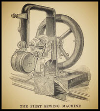
As reproduction of historical newspaper articles and/or historical sources and/or historical artifacts, this works may contain errors of spelling and/or missing words and/or missing pages and/or poor pictures, etc.