Room 14
Recent Advances in Sewing Machinery
by John W. Urquhart
1887
The distinct improvements in sewing machinery, to which I would invite your attention this evening, have reference more particularly to the results of inventive effort within the past ten years. But although marked development in the machines has occurred in so short a time it may be taken for granted that those advances are but the accumulated results of many years' prior invention and experience of stitching appliances. The history of the sewing machine and the decision of the great question " who invented an apparatus that would unite fabrics by stitches ? " do not at present concern us. Many sources of information are open to those who would decide that extremely involved problem. But whether the production of the first device of this kind be claimed for England or for America it is quite certain that no one man invented the perfect machine and that those fine specimens of sewing apparatus shown here to-night embody the labours of many earnest workers both in Europe and America.
Most of us are familiar with the arrangements of an ordinary lock-stitch machine and an able paper by Mr. Edwin P. Alexander, embracing not only a good account of its history, but most of the elements of the earlier machines, has already (April 5 th, 1863) been read before you. This and sundry descriptions of such apparatus in the engineering papers confine my remarks to the more recent improvements in three great classes of machines. These are, briefly, plain sewing machines; sewing machines as used in factories, where they are moved by steam power and special sewing machines, embracing many interesting forms, only recently introduced. We have thus to consider, in the first place, the general efficiency of the machine as a plain stitcher; secondly, its adaptability to high rates of speed and the provision that has been made to withstand such velocities for a reasonable time and, thirdly, the apparatus and means employed to effect the controlling of the motive power when applied to the machines. To deal with the subject in this way must, I fear, involve a good deal of technical description and I hope to be pardoned if in attempting to elucidate the more important devices use must be made of words but seldom heard outside of a machinists' workshop. It appears scarcely necessary to premise that the sewing machine of twenty years ago has almost faded away, save, perhaps, in general exterior appearance.
That the bell crank arms, the heart cams, the weaver's shuttles, the spring "take ups", rectangular needle bars and gear wheels, have developed into very different devices for performing the various functions of those several parts.
The shuttle is perhaps the most important part of a lock-stitch machine. But what is a shuttle? So many devices for performing the functions of the early weaver's shuttle have been introduced of late that the word shuttle, if it be used at all, must not be accepted as meaning " toshoot ". We have vibrating shuttles, which are, strictly speaking, the only surviving representatives of the weaver's shuttle in these new orders of machines and stationary shuttles, oscillating shuttles and revolving shuttles, besides the earlier rotating hook, in several new forms difficult to name. But the general acceptation of the word shuttle, as indicating those devices that pass bodily through the loop of upper thread, is, I venture to think, sufficiently correct. Many changes have been effected in the form, size and movements of the shuttle and we may profitably inquire into the causes that have induced manufacturers to abandon the earlier forms. The long, weaver's kind of shuttle, originally used by Howe and Singer, had many drawbacks. Mr. A. B. Wilson's ingenious device, the lock-stitch rotating hook, was not free from corresponding faults. The removal of these in both has led to the adoption of an entirely new class of both shuttles and revolving hooks. It is well known that the lock-stitch is formed by the crossing of two threads, one of which lies over and the other under the cloth to be sewn. This crossing point, to insure integrity of the stitch, must occur as nearly as possible in the middle of the thickness of the fabric. The crossing must also be effected while a certain strain, called tension, is imposed upon both threads. If the tension jof one thread should outweigh that of the other the locking point becomes displaced; if the tension be insignificant the stitches will be loose; if the tension should vary, as in the long shuttle, there will occur faulty points in the seam.
In the earlier rotating hook the tension depended upon the friction developed between the spool and the hook. This tension, therefore, varied in proportion to the speed of the latter and could never be constant. This was quite apart from the frictional resistance offered to the upper thread in passing over the cavity of the hook. In the shuttle the tension was obtained by threading through holes in the shell, or beneath a tension plate, as in Howe's machine. This tension, so long as the reel ran between spring centres, was never constant. The variation was chiefly due to the angular strain set up when unwinding from the reel. This strain varied according to the point of unwinding. It was light in the middle of the reel and heavy at either extremity. These drawbacks caused immense anxiety to the first makers of sewing machines and numerous attempts to overcome them led to little improvement. With reference to high rates of speed, the older shuttle, requiring a long and noisy reciprocation, had its disadvantages. The only effective remedy for these drawbacks was a radical one. It was necessary to substitute depth of reel for length. Hence several attempts have been made to construct disc or ring shuttles. Many forms of those have been tried. They all depend upon the principle of coiling up the thread in a vertical plane, rather than in horizontal spirals. Some makers placed the disc in a horizontal plane and caused it to revolve. Nothing could be worse, as will be seen, if we follow the course the enveloping loop must take in encircling such a shuttle. But a complete solution of the difficulty of employing a ring shuttle has been achieved in the oscillating form invented by Mr. Phil Diehl and known as Singer's (Fig. 1).
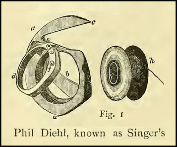
A short examination of it may profitably engage your attention. The shuttle itself is sufficiently well known, but certain features of it and to which it owes its efficiency, appear to call for some explanation. Its introduction dates back some years, during which time it has undergone certain modifications. It consists of a thick disc bobbin of thread, A, fitting loosely in a case constructed in the form of a bivalve, a and d. This case is furnished with a long beak, usually forming a continuation of the periphery. The beak is intended to enter and detain the loops of upper thread and lead them so that they ultimately envelop the shuttle, a motion of the thread which is chiefly due to the oscillation of the shuttle in a vertical plane. The oscillating movement is to the extent of 180 degs. of the circle, which suffices to cast the loops freely over the shuttle. The centre of oscillation is not coincident with the centre of the shuttle; but it is nearly so with the periphery of the thread reel and exactly coincides with the point where the under thread is drawn from the shuttle, g. The shuttle thread is thus entirely freed from any tendency to twist, an objection frequently urged against circular or revolving shuttles. It will be observed, also, that the body of the shuttle is extremely narrow. Bulging of the thread loops to one side or the other is thus obviated
But the long beak in this description of shuttle serves an important purpose other than that of seizing the upper thread loops, otherwise a very short beak would be preferable. It adds so much to the efficiency of the machine that a little further explanation of it appears essential. In the old-fashioned machines the thread required to envelop the shuttle was dragged downwards through the cloth, while the needle still remained in the fabric. This necessitated the use of large needles with deep side channels, to enable the thread to run freely and, as a consequence, the punctures that had to be made in the fabric were unnecessarily large and could not in any case be entirely filled by the thread, a condition which is now recognised as essential in linen stitching and for waterproof boots. The long beak in both shuttles and hooks offers an immediate solution of the old difficulty experienced with long shuttles. When the needle begins to rise, the shuttle commences to oscillate through the loop, the motions so coinciding that the long beak, c, merely detains the loop until the eye of the needle has ascended above the cloth, then and then only, does the envelopment of the shuttle commence and the thread required for it flows downwards through the puncture. The envelopment is completed before the needle has attained its highest point and the consequent loose thread is immediately pulled up by a lever, called a positive take-up, before the needle begins to descend for a fresh stitch. In this way little or no movement of the thread is required in the cloth while the puncture made is occupied by the needle. The result is the capability of such an apparatus to work with an incredibly fine needle, indeed, so fine as to be no thicker than the uncompressed thread itself. This would have been considered quite impossible of accomplishment by our earlier machine makers. The advantage thereby gained in stitching linen goods and in sewing leather, where every puncture of the needle should be quite filled by the thread, is at once apparent. Indeed, a rubber or leather sack, stitched in this way, will contain water without leakage, a very extreme test.
Revolving Shuttles
The class of shuttles known as revolving or rotating and which really consist of a combination of the disc shuttle and the earlier rotating hook of Wilson, have been under trial by several makers for many years. If, for example, the oscillating shuttle we have just examined were to complete its circular movement, it would constitute a revolving shuttle, but would not be quite similar to those devices now known as such. The most remarkable device of this kind yet introduced is to be found in Wheeler & Wilson's machine known as No. 10 D and invented by Mr. Wilbur F. Dial last year (US 350.044 ???). It consists, in fact, of a detached hook and its inventor declines to class it with shuttles at all, styling it a detached hook. It consists of an exterior shell or skeleton of steel, capable of rotation in an annular raceway. Its detachment from the axis forms a striking exception to the general construction of interlocking apparatus in this company's machines. Under the beak of this curious device is found an oblong recess, into which fits, loosely, a carrier or driver, rotating with a differential or variable motion. The space between the carrier and the sides of the recess is sufficient to permit the free passage of the thread in encircling the shuttle. The skeleton of this device is only one-sided and does not really carry its bobbin in the course of its revolution. The bobbin is placed in a cup-like holder, which lies within the shuttle or hook body and is retained in position by a latch hinged to the bed of the machine. The cup and bobbin are prevented from partaking of the rotatory movement by a steel spur projecting from the cup and fitting loosely into a notch in the latch; tension upon the under thread is obtained by passing it under a tension plate upon the bobbin cup. Twisting of the thread is by these means entirely obviated. In this apparatus the disc-like appearance of the bobbin is partially lost in its considerable breadth and there is thus a distinct departure from the lines of the ring shuttles before mentioned. The diagrams exhibit the shuttle in several positions during its revolution and the position of the threads corresponding thereto.

Rotating Hooks
Wilson's rotating hook for lockstitch machines and Gibbs' hook for single-thread machines, are both well known. In the year 1872 the Wheeler & Wilson Company introduced a new hook, forming an improvement upon Wilson's original device (Fig. 3).
Its chief peculiarity consists in the extension of the termination of the periphery, forming a long tailpiece quite overlapping the point and serving as a guard, both to keep off the bobbin thread and to prevent collision between bobbin and needle. This improved class of hooks are provided with a much deeper cavity than those first introduced, an arrangement permitting of the employment of a more commodious bobbin, which is generally covered by a cap, as in the revolving shuttle, but free to revolve. In some cases the cap carries a tension plate, preventing its revolution with the hook.
But beyond these improvements on Wilson's original device, the utility of the hook mainly depends upon two things quite apart from the hook itself. These are the dispensing with the old-fashioned check brush and the use of a positive take-up. Thus, in the original machine the stitch was pulled up by the succeeding revolution of the hook. For while one revolution sufficed to cast it over the spool, a second turn was requisite to complete the stitch. In this way to make a first stitch with such an apparatus required two turns of the rotating hook. The improvements mentioned enable the machine to complete a stitch with one turn of the hook, an important step in advance, when we consider that by the old method each length of slack thread must be tightened up solely through the fabric and the needle eye.
But this particular arrangement bears so much upon the introduction of the positive take up itself that further reference to it must be reserved until that device has been described.
Simple Thread Hooks
The best known of these is Wilcox & Gibbs. It has been so often described that no further reference to it may be made. It continues to make the same excellent twisted stitch as it produced twenty-five years ago.
Of Vibrating Shuttles
These are shuttles of the long description, moving in a segment of a circle. There are several varieties; the most novel machine of this kind is the vibrating shuttle machine just produced by the Singer Manufacturing Company. In this case the shuttle itself consists of a steel tube, into the open end of which the wound reel is dropped and is free to revolve quite loosely. Variation of tension is thus obviated in a very simple manner. The chief point of interest in the machine is undoubtedly the means employed in transferring the motion from the main shaft to the underneath parts, an arrangement certainly as ingenious and effective as any device ever introduced into stitching mechanism. It is the invention of Mr. Robert Whitehill and consists of a vertical rocking shaft situated in the arm of the machine. Motion is imparted to it by means of an elbow formed upon the main shaft, acting upon two arms, called wipers, projecting from the rocking shaft, the angle formed by the arms exactly coinciding with that of the elbow in its revolution. This admirable motion will no doubt attract much attention from mechanists and engineers.
The Lock-stitch from Two Reels
In the early days of the sewing machine the makers of it often met with the question, " why do you use a shuttle at all ? Can you not invent a method of working from the reel direct ? "
The questioner generally means a reel placed upon a pin, just as the tipper reel is placed. The reply to such a query is, of course, that to produce the lock-stitch in that way is impossible, as indeed it is. But many ingenious machinists have pondered long over the problem and several clever contrivances have been invented with a view to its solution. It may scarcely be necessary to say that the best manufacturers of sewing machines have conducted experiments with the same object in view and the result has always been a return to the shuttle, with its steel bobbins. Why is this and how is it that a very big shuttle cannot be used, large enough, indeed, to accomodate any bobbin within itself ? The answer is very simple. It has been done over and over again. Since the whole bulk of the under thread must pass through the loop of the upper one, it is quite clear that the size of that loop must be proportioned to the bulk of the shuttle. Thus, a small shuttle would, perhaps, be covered by an inch of thread, while our supposed mammoth shuttle might require ten times that amount. Now, let us consider that to sew an inch of thread into lock-stitches frequently involves its being drawn up and down through both needle and fabric twenty times. This means considerable chafing and possible injury to the thread.
But if we were to sanction the use of capacious shuttles, ten inches of thread must undergo this chafing and seesaw treatment and under the above conditions every part of the ten inches must pass up and down two hundred times, treatment that might reasonably be expected to leave little "life" in the thread. But, in spite of this tremendous drawback, there are machines offered for sale made with such shuttles. For reasons that I have now pointed out, it is quite clear that a large shuttle or bobbin is by no means an unmixed advantage. Indeed, the very best makers of sewing machines have always striven to keep down the bulk of the shuttle and in those splendid machines shown here to-night the use of the small shuttles is conspicuous. It may be contended that small bobbins frequently require refilling, which is quite true, but the saving of the thread effected thereby, not to mention that of the machine itself, amply compensates for the use of small shuttles. Apart from this, however, it is no longer necessary to wind bobbins at all.
Dewhurst & Sons, of Skipton and Clark & Co., of Paisley, have produced ready wound " cops " or bobbins of thread for placing direct into shuttles. Thus no winding of bobbins is necessary and indeed the bobbins themselves are dispensed with. I believe that the slightly increased cost of the thread thus wound is the only present bar to the extensive introduction of ready wound "cops".
Of Thread Controllers
One of the earliest difficulties encountered by the maker of a sewing machine was that of effectually controlling the loose thread after it had been cast off the shuttle. In some machines this slack thread amounts to six, in others to one or two, inches. Howe got over the difficulty by passing his thread, on its way to the needle, over the upper extremity of the needle bar, the ascent of the bar then sufficed to pull up the slack.
Singer improved upon this by furnishing his machine with a spring take-up lever, partially controlled by the needle bar.
Wilson, in the Wheeler & Wilson machine, had neither of those arrangements, but depended upon the succeeding revolution of the hook to draw up the slack of the preceding stitch.
These devices were all far from perfect in their operation, chiefly because they commenced to act too soon. In each case the pulling up commenced with the rise of the needle and the tightening operation subjected the thread to all the friction of rubbing its way through both needle-eye and fabric. Now, an ideal take-up should not commence to act until the needle has ascended above the fabric and one of the most important steps towards perfection in sewing machines was undoubtedly attained when such a device was actually invented. In effecting this the means employed consisted of a differential or variable cam, rotating with the main shaft. This controlled the movements of a lever called the take-up, pivoted to the machine (Fig. 4).

Not only has it been possible by these means to control the tightening of the stitch, but the paying out of the thread for enveloping the shuttle also and both the paying out and pulling up are actually effected after the needle has ascended above the cloth. The introduction of the positive take-up, the first forms of which appeared in 1872, not only simplifies the movements of the shuttle or hook, but for the first time renders the making of the lock-stitch possible, while the needle has a direct up and down-motion. Thus we find that in most of the swiftest sewing machines the needle-bar is actuated by a simple crank-pin, or eccentric, there being no loop-dip or pause in its motion. The diagram shows the positive take-up in three positions; at the commencement of the needle's descent, during the detention of the loop by the beak and during the casting off of the loop. The dotted lines indicate the path of the cam to produce these positions. The intermittent movements of the take-up have thus led to the abandonment of variable motions in both needle and shuttle and particularly so in oscillating shuttle machines.
Wheeler & Wilson's Variable Motion
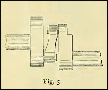
But while the simple and direct movement is now preferred for shuttles, both oscillating and rotary, the revolving hooks of Wheeler & Wilson are provided with a differential motion and the way it is effected appears sufficiently interesting to call for a short description. When the rotating hook has seized the loop of thread it makes half a revolution with great rapidity; its speed then slackens and becomes very slow for the remaining half a revolution. In the first machines introduced this was effected by means of a revolving disc, having slots, in which worked pins attached to the main shaft and hook shaft respectively. In the later and more improved machines the variable device is much simplified (Fig. 5). The main shaft, leading to the rotating hook, is separated into two portions, the axis of one portion being placed above that of the other. A crank-pin is attached to each and these pins are connected together by a simple link. An examination of the device itself shows that, while the motion of the main shaft portion is uniform, that of the hook shaft is alternately accelerated and retarded. The picture on the screen gives a general view of the W & W No. 10 D machine, in which these motions are embodied and showing the position of the positive take-up affected by those motions; a position which is preferred for very high speeds in this machine, especially for threads possessing little elasticity
Motions of the Feeder
The speed attained by the fastest sewing machines is due more to the reduction and simplification of the movements than to any other improvement. Heavy concessions and reactions have been replaced by direct motions and cams have been excluded as much as possible. Mr. A. B. Wilson's famous invention of the four-motion feeder depended upon both gravity and a reacting spring for two motions. Singer improved upon it by making three of the motions positive, a spring being used for the drop. But a really positive four-motion feeder was long sought by inventors. Hitherto the reaction of the feeder, that is, its descent and recession, was generally attained by means of a spring. The drop and ascent are now effected by means of a separate eccentric in Singer's machine. Uncertainty of action in the feed, once a cause of much inconvenience, may now be said to be overcome. A peculiarity of the four-motion feeder in Wheeler & Wilson's machine is an arrangement enabling the operator to feed in either direction at will. Not less worthy of note are improvements that have been made in wheel-feeders. The wheel-feed was originally much used for cloth sewing machines, especially in Singer's system; but in recent years the drop or fourmotion feeder has entirely superseded it for such purposes. The wheel-feed still holds its own, however, for sewing leather, especially in the "closing" of boot uppers, in this country. Singer's original wheel-feeder was actuated by a friction shoe riding upon the flange of the wheel. The friction grip, however, had certain faults, owing to the tendency of the shoe to slip when the surfaces became covered with oil. A later form of Howe's machine used a pair of angular clutches, embracing the flange of the wheel. In both Singer's and Wheeler & Wilson's latest styles of machines this arrangement is simplified and improved by the use of a single angle clutch, which is found to work even when the surfaces are freely oiled (Fig. 6).

Any motion of the free extremity of the lever upon which the biting clutch is formed binds the latter upon the flange of the wheel, which then advances so long as the lever continues to move in that direction. When the stitch is completed the clutch is allowed to recede and is pulled back by a reacting spring. The bite of the clutch is given by the two opposite corners. The feed-wheel itself is free to revolve in a forward direction, but is prevented from rocking backwards in Singer's machine by an ingenious little device, recently introduced. It consists of a small steel roller, situated within the angle formed by an inclined plane and the flange of the wheel and constantly pulled into the angle by a spiral spring. Any backward tendency of the wheel binds the roller more firmly in the angle and stops the wheel. Former feed-wheels were checked by a brake spring or block, which retarded the motion of the whole machine when heavily adjusted. Feeders for button-hole sewing machines are almost invariably of the wheel type, but in this case the cloth is usually carried by a clamping device and moved in a pear-shaped path by means of a cam cut in the feed-wheel, as shown in the samples of this wonderful kind of mechanism exhibited here to-night.

The Compensating System of Construction
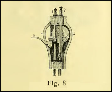
Compensation for wear is a part of the mechanist's art that appears just as essential to him as compensation for variation of temperature are to a maker of chronometers. In the construction of sewing machines to be run in factories by power at their utmost speed such a system is of the greatest importance. An effective system of compensation has been eagerly sought by the best machine makers ever since the introduction of fast-speed sewing. Compensation has been attempted here and there in the machines for many years, but no sewing apparatus could be said to be so compensated until the cone compensator came into use, a device which has been taken advantage of by various makers. Save in the shuttle race itself there' is not a part of the oscillating shuttle machine subject to serious wear that cannot be instantly adjusted to full motion by the turning of a screw, while wear in the shuttle race can be compensated for in the usual way. This effective system depends upon the union of two mathematical forms, long used in mechanism, the cone and the screw. In screw-cones we possess a perfect compensator and it is surprising that parts of mechanism so hung appear subject to very little wear. Another advantage, too, is gained by the introduction of screw-cone bearings; the friction is always greatly reduced by their use. In every case the fine adjustment of the cones is securely maintained by locknuts (Fig. 7). But the screw-cone system is not the only compensator used in sewing machinery; where it cannot be easily introduced, other devices have been employed. The well-known tapering needle bars of former years have been superseded by cylindrical needle-bars. The Wheeler & Wilson Company appear to be the first who utilised the engineer's shifting hox as an anti-friction device for round needle-bars. They packed their bars round with felt rings and compressed the whole by a screw-cap. In the Singer machines the same excellent device has been adopted, hemp packing and screw bushes being used (Fig. 8) f and g show the direct action on the needle-bar. This method of forming needle-bar bearings, partially of metal and partially of felt or hemp, has afforded the most surprising results. When the bars are of hard or finely-polished steel no perceptible wear can be detected in them, even after they have been in daily use in factories for twelve months, whereas bars not so bushed might show considerable wear in that space of time. The packing, to be effective, should be sufficiently close to prevent as much as possible friction of the steel with the cast-iron needle-bar ways. Lubrication of the steel is ensured by keeping the hemp packing moistened with oil.
Cylindrical needle-bars, when combined with an effective system of brushing, have proved themselves superior to every other form of slide for lock-stitch machines. But their introduction is by no means a thing of yesterday. They were used freely in sewing machines as far back as 1860, but were never very successful until united with the lubricating brush. Some makers go a step further and elaborate the system by the introduction of steel brushes, easily renewable. Every effort is now made to reduce, as much as possible, not only the extent of movement of the parts in high speed machines, but the weight of the parts themselves; indeed, so far has this been carried that in some of the Wheeler & Wilson machines now shown the needle-bars consist really of steel tubes. Small moving parts are made as light as possible, but rigidity is secured by the free use of strengthening ribs. Many of the parts are of cast iron, rendered malleable by annealing and finally case-hardened. Such parts are found to be quite as durable as if made of forged steel and are, of course, less costly. As to the automatic tools now used in the construction of the machines, it may be said that scarcely a file, hammer, or chisel touches the frame or parts while they are being assembled to work together. The interchangeable system of construction is, of course, the only one possible for the accurate production of the millions of sewing machines now manufactured annually.
High Arm Construction
Sewing machines, as now constructed, exhibit a rather short and very high arm, a form of framework that has been found to contribute in no small degree to the light running capabilities of fast speed machines. While it reduces the length of the various parts concerned in the transference of the motive power it adds to their rigidity and diminishes their weight, maintaining at the same time the capacity of the machine to accommodate the largest garments beneath the arm. But the specific improvements in plain sewing machines, to which I have had the honour of drawing your attention, do not exhaust the list and, time permitting, it might be considerably augmented. Nor must it be inferred that advancement has taken place exclusively in those systems of sewing machinery now before us.
Accessories to Serving Machines
The number of special attachments that have been successfully adapted to plain sewing machines has multiplied so rapidly of late that only one or two of the more notable can be spoken of on this occasion. Perhaps the most generally useful of these is the trimmer, an arrangement consisting of a vibrating knife, which trims off the superfluous edge of a seam as the machine stitches it. These are in extensive use in the factories at Leicester, Nottingham and elsewhere, while Northampton and Norwich use the same device for paring the seams in boot-upper manufacture. The chisel-like knife is usually actuated by a cam rotating with the main shaft and one or two of the usual forms of this attachment are to be seen here this evening on both lock and loop stitch machines. When machines are moved by the foot there are many objections to running the whole machine while winding the shuttle reels. We have, therefore, several useful devices for releasing the balance wheel of the machine from the main shaft while winding. These are to be found both on Wheeler & Wilson's manufacturing machine and upon Singer's highly-finished " family " machine, which also carries a most ingenious automatic reel winder, capable of doing all the work itself and ceasing to act as soon as the bobbin is filled. The setting of the needle in a sewing machine was once quite a task. often it had to be adjusted by chance, in other instances by certain guiding marks upon the needle-bar.
It is gratifying to know that all this has been done away with and that the needle has only to be inserted into the bar and fastened by turning a small screw. These are styled self-setting needles and are usually so arranged that they cannot be adjusted wrongly as to the position of the eye. In the Wilcox & Gibbs machine, and in Singer's single-thread machine, shown here, we have an intermittent tension arrangement, which clamps the thread at the right moment and differs from ordinary tension devices, inasmuch as it may be said to be automatic. The feeder, too, on these machines is of excellent design, while the arrangements that have been introduced into the Wilcox & Gibbs straw-hat sewing machine arc surprisingly effective in spinning up a hat from a loose roll of braid. Speaking of straw-hat machines, mention should be made of Wiseman's hand-stitch apparatus, as improved by Messrs. Wilcox & Gibbs and shown here this evening. This machine employs two needles and makes a stitch resembling hand-work at intervals, producing a short stitch at the centre of the hat and automatically widening the space between the stitches as the distance from the centre increases.
The machine itself is of wonderful ingenuity and must be examined to be understood. The stitch-making itself is, I believe, quite new and is also of much interest. A pair of needles, the width of a stitch apart, rise from beneath, through the material; one of these is an ordinary machine needle, threaded; the other is a barbed needle. After rising above the surface the loop of the threaded needle is seized by a "threader" and thrown into the barb of the barbed needle. The needles then descend and the feed occurs, being the length between stitches. Upon the ascent of the needles again against the material the loop is both given off the barb and is entered by the threaded needle, completing the stitch.
Of Button-hole Machines
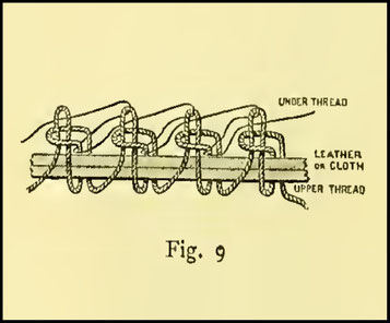
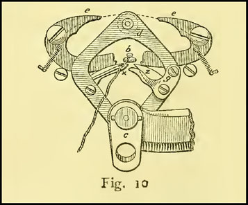
The mechanism of buttonhole machines is so intricate that I can only attempt on this occasion to partially elucidate the construction of one of them, recently introduced, namely, Singer's, which automatically cuts, guides and stitches the work. Fig. 9 exhibits the stitching made by this machine upon the edge of the button-hole and Fig. 10 represents the right and left hand loopers and loop spreaders and for the stitchmaking. They rock from right to left with an intermittent motion obtained from a cam. The left-hand looper carries the under thread and interweaves it with the upper, forming the stitch, originally invented, I believe, by Mr. George Fisher, of Nottingham (England) and reinvented for the buttonholing machine by D. W. G. Humphreys, of Massachusetts, United States of America, in 1862 (US 36.617). The loop spreaders are moved by a roller carried upon the looper frame.

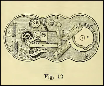
Fig. 11 exhibits the feeding arrangement, both sides of the feed-wheel, the driving lever and the shape of the path given to the carrying clamp by the heart cam cut in the upper surface of the feed-wheel. The picture on the screen represents the upper portions of the machine, exhibiting the conveying clamp, the too and fro dipping motions of the needle-bar and the parts conveying motion to the arrangements beneath the bed-plate. These are shown in Fig. 12 and represent the feed and looper cams, the feeding and looper levers and the stitch forming mechanism already shown. A most ingenious device in this machine is the arrangement for automatically lengthening the throw of the feed while stitching around the eye of the button-hole. It is effected by means of a cam, which imparts more or less leverage to the feed-arm by the intervention of a "shipper" lever, hinged to the feed-lever itself. The space of time at my disposal obliges me to recommend a personal examination of the machine itself, to fully understand its various motions and its action in working a button-hole. Mention may be made of Singer's special button-hole machine for making the straight holes used in linen work and in which a shuttle is employed. Of Wheeler & Wilson's ingenious button-hole machine for the same purpose I am enabled to show a diagram, in which it will be observed that the feeding arrangements are placed above the bed-plate and are no doubt thereby rendered easily accessible.
Application of Power to Sewing Machines
There was a time when a cry arose to the effect that the introduction of mechanical sewing would lead to divers calamities, physical and mental. The ladies were to become crooked in the spine and regular operators were to become regular cripples. It is scarcely necessary to ask has this been so? The operators of to-day are, I think, superior in physical attainments to their sisters of the needle and thread fifty years ago. Within the past few years a revolution has taken place in the moving of sewing machines. Domestic machines will probably always be driven by foot power; spring, electric and water motors notwithstanding. But the age of treadles in the great manufacturing trades is a thing of the past. It was not necessary for Parliament to step in and protect the workers, as was frequently suggested by alarmists. The commercial interests of manufacturers themselves were at stake. Machines driven by power could do 25 per cent, more work than those moved by foot. The operators, relieved of the treadling, maintained a much better working condition and altogether the introduction of power driving, once well tested, became a necessity. Power sewing machinery was speedily devised and introduced by several of the first manufacturers, controllers of the speed of the machines followed and two or three splendid systems of stitching by steam power were soon widely known.
By the kindness of three of the best manufacturers of power sewing machinery, I am enabled to show to you, this evening, the best-known systems, arranged just as they are fitted in many large factories, as also a sketch of the arrangements of Wheeler & Wilson's system. We have, in the first place, a light shafting carrying a band wheel opposite to each machine. By the use of a powerful electro motor the shafting is caused to rotate at the rate of 400 revolutions per minute by electricity. The current is generated by the society's dynamo machine and is conveyed here by copper cable. I do not know of any instance of sewing machinery in a factory being driven by an electro motor, but such means of conveying motive power appears admirably adapted for that purpose, when the stitching room happens to be far removed from the main shafting or engine. But with regard to motors for sewing machines, when special power has to be fitted down for that purpose, my own experience leads me to speak in favour of the admirably governed "Otto" gas engines made by Crossley Bros. These are especially steady, a feature of no small moment in moving stitching machinery of various kinds.

Much attention has been devoted to the invention of controllers of the motive power supplied to sewing machines. The principle of the friction disc has found most favour. In many cases two of these plates, fast and loose, are placed upon the main shaft and their separation and contact controlled by the treadle. The great sensitiveness of the friction attachment employed by the Singer Company is due chiefly to the transference of the friction plates to the axis of the machine itself (Fig. 13). Their contact and separation are controlled by a lever worked by a very slight movement of the treadle. But the chief point of interest in this device lies in the combination with the lever of a brake, enabling the operator, by a simple reversal of the treadle's motion, to instantly suspend the rotation of the machine. The forked lever, in fact, acts simultaneously in throwing off the motion and applying the brake.
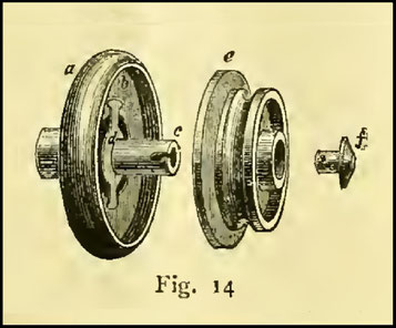
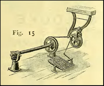
The speed is always in direct proportion to the pressure exerted upon the treadle and a single stitch can be made at will. Fig. 14 shows the friction wheel separated, the portion a being fast and e loose. The Wheeler & Wilson Company do not confine themselves to any particular controller, but prefer the form shown here this evening (Fig. 15), in which two bands and an intermediate pulley are employed. The first band is left rather loose and the machine is set in motion by the tightening of this band through the depression of the treadle. The speed varies in proportion to the pressure applied and the sensitiveness of the arrangement is increased by a brake device coming into play by the reversal of the treadle as before. Messrs. Wilcox & Gibbs depend upon a similar device shown in three varieties to-night.
Speed of Power Sewing Machines
The fastest practicable speed of a machine worked by the foot appears to be 1.000 stitches per minute. Most operators can guide the work at a much higher rate, especially in tailoring or on long seams. The average speed upon such work is 1.200 stitches per minute; but many lock-stitch machines are run at 1.500 and 1.800 per minute and even at much higher rates.
There is always a limit to be imposed upon speed by the guiding powers of hand and eye; it is this limit and not the capability of the machine, that confines the rate of driving. Wilcox and Gibbs' single-thread machines are run in many instances at 3.500 stitches per minute. We have before us a single-thread Singer machine (appropriately named the " Lightning Sewer ") and a Wilcox machine, moving at the enormous rate of 4.500 stitches per minute and producing good work. But it is doubtful whether such very great velocities can ever be advantageously employed. Upon collar work and in sewing boot uppers, the rate seldom rises above 1.200 with advantage. If the machines be speeded too high in any trade, the operator never uses the excess and it only proves a drawback. I have seen the heaviest and hardest kind of navvy boots stitched at 1.500 to the minute upon Singer's lockstitch machines.
Wheeler & Wilson's No.10 D machine has been run by them, I am informed, as high as 2.500 to the minute. Loop-stitch machines, when well made, can be actually run as high as 6.000, but 4.500 is, I believe, the maximum yet used for this class of machine even experimentally. There can be no doubt that lockstitch machines can be run as high as 3.000. The actual speeds of the lock-stitch machines shown here upon the power stand averages 1.300; those of the chain-stitch machines varies from 1.200 for the sack sewing machine to 4.500 for the small or single chain stitchers. Any of the latest styles of either lock-stitch or single-thread machines can be run far faster than any known expert operator can possibly guide the work under it. It is very improbable that such speeds will ever be exceeded. The limit has no doubt been reached. Very high speed is generally a delusion and either results in indifferent work, or actually retards its progress. Some idea of the speed of the single-thread machines, now shown, may be gathered from the fact that, running at 4.500 and making eight stitches to the inch, they accomplish over fourteen yards of sewing every minute. Of special machines of interest and which are too unwieldy to be shown here, I am enabled to exhibit a few photographs. One of the most novel of these is the "Twin " machine, designed by the Singer Company, for the connecting together of the Jacquard cards used in lace machines. The operation was formerly performed by hand. It is now done by machine at less cost. The cards are placed upon a feeding drum and fed beneath a pair of needles. The laces forming the connection between the cards are fed above and beneath, in line with the needles and the whole is easily stitched together. An extension of the same device is the multiple machine, in which four needles and shuttles are used, sewing all the four seams at one operation. This method of linking the cords is considered better than similar work done by hand. Before drawing my remarks to a close, I would briefly indicate the nature of the various machines shown upon the power benching.
Of the Singer system there are four:
1. a drop-feed oscillating shuttle machine for manufacturing purposes;
2. a wheel-feed oscillating shuttle machine, furnished with a trimmer, used chiefly in stitching leather and boot uppers;
3. double chain-stitch machine, used for sackmaking, now shown for the first time;
4. a single-thread " Lightning Sewer", fitted with a trimmer for hosiery work.
Of Wheeler & Wilson's system there are three:
1. a drop-feed manufacturing machine with the new detached hook and latest improvements;
2. a No. 10 machine with the usual hook, a wheel feed and trimmer;
3. a smaller machine of the same type with drop-feed.
Of Wilcox & Gibbs' system there are three:
1. the ordinary single-thread machine for manufacturing;
2. a single-thread machine, with a trimmer, as used in the hosiery trades;
3. a machine specially used for straw hat making.
We have here a small Singer machine, riding upon the edge of two pieces of carpet, a carpet machine weighing ten pounds. When the handle is turned it stitches and travels over the edges, uniting them faster and more securely than six hand-sewers and several others, representative of the family type of sewing machine, besides Wheeler & Wilson's hem-stitch machine, the working of which is of much interest. Mention should be made of the revolving shuttle, to be found in the Standard machine, shown by Mr. Carver, which appears to have all the advantages of the disc type and is certainly adapted for a high rate of speed, even by treadle. The shuttle partakes of a variable motion imparted to the under shaft, as in Wheeler & Wilson's machine. The head is furnished with a positive take-up and a direct needle motion.
I would now invite those of you who seek a better acquaintance with those curious and novel machines to freely examine and test the various types to be found upon the power benching and upon stands. One or two operators will come forward and show some of the capabilities of the machines upon actual work, in which the making of a straw hat will perhaps show what can be done in a few minutes by quick speed and expert fingers, but these performances must not be regarded in the light of competitive tests between the manufacturers showing them and are intended merely to show the utility of motive power driving.
In conclusion, I desire to thank those gentlemen at the head of the leading firms of sewing machine manufacturers for the trouble they have taken to arrange for your inspection specimens of their excellent systems and for ready assistance in the preparation of my paper.
Read before the Society of Arts, February 23rd, 1887. For the loan of woodcuts we are indebted to the Society of Arts.
The Sewing Machine Gazette - March, 1887
As reproduction of historical newspaper articles and/or historical sources and/or historical artifacts, this works may contain errors of spelling and/or missing words and/or missing pages and/or poor pictures, etc.